background image

SH-MF1 Training

54

Slide 54

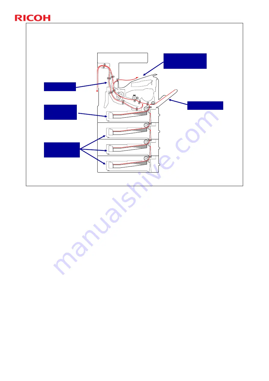
Paper Path – Basic Model

Bypass Tray

Standard 
Paper Tray

Standard Paper 
Exit Tray

Duplex unit

Optional 
Paper Trays

ˆ

This slide shows the paper path for the basic model (M052) with three optional 
paper trays installed.

Summary of Contents for M052

Page 1: ...H MF1 Training 1 Slide 1 MODEL SH MF1 TRAINING Machine Codes M052 M053 M054 Version 1 0 This course is for the SK MF1 series of copiers Modifications Started 12 January 2011 Release version 8 March 2011 ...

Page 2: ...cifications Options Installation Transporting the Machine Maintenance Machine Overview ARDF Scanner Paper Feed Laser Exposure All In One Cartridge AIO Fusing Paper Exit Duplex Optional Paper Tray Units M375 M376 Internal Finisher M054 only One bin Tray M053 only Environmental Conservation ...

Page 3: ...SH MF1 Training 3 Slide 3 PRODUCT OUTLINE Introduction No additional notes ...

Page 4: ...ning 4 Slide 4 Machine Concepts Product Placement 45 50ppm Concepts 1 There is not a predecessor model New engine 2 New AIO was developed to achieve B W 45 50ppm 3 User install User maintenance No additional notes ...

Page 5: ...n SH MF1m fax model Copy Print Scan Fax 1 Bin tray SH MF1f finisher model Copy Print Scan Internal finisher SP5210SR Aficio SP5210SR M054 SH MF1f SP5210SF Aficio SP5210SF M053 SH MF1m SP5200S Aficio SP5200S M052 SH MF1 Product Names Code Model Name Table SH MF1m m modem SH MF1f f finisher ...

Page 6: ...1090 M375 The ARDF internal finisher and operation panel are the same as those used on the Model Z C1 series All three models come with one paper tray If installed on the floor up to three paper feed units can be added as options with a maximum of two TK1090 units The lowermost paper feed unit must be TK1100 has casters If installed on a desk table only one TK1090 unit can be installed The standar...

Page 7: ...1a b g type J K 2 Option Option Gigabit Ethernet board type A Standard Standard HDD 128 GB 1 GB memory Option Option Paper feed unit TK1090 Standard Standard Option Standard N A Standard Basic Model M052 Standard Standard Standard Standard Standard Standard 1 Bin Fax Model M053 NIC USB 2 0 USB host PS3 PDF direct print Fax option type SP5200 SD USB card slots One bin Tray ARDF Function Feature Equ...

Page 8: ...d VM card D377 B829 D571 D430 Code Option Option Key card I F Option Option File format converter type E Option Option Copy data security unit type F Option Option IPDS unit type 5210 Option Option Browser unit type E Basic Model M052 1 Bin Fax Model M053 Function Feature This slide shows more of the available equipment for each model This machine is compatible with Remote communication gate type ...

Page 9: ...nd M054 units the panel can be tilted for better viewing The panel cannot be adjusted on M052 units Tilt Operation Panel Operation Panel 8 5 inch color LCD This is the same operation panel as used by Model Z C1 series M022 M024 M026 M028 ...

Page 10: ...lide 10 Internal Finisher Standard equipment for the finisher models but not available as an option for the standard models The staple cartridge can be changed easily Internal Finisher Staple Cartridge No additional notes ...

Page 11: ...stalling the Card Reader Space for installing a card reader is shown above The IC card reader is not supplied by Ricoh and must be procured locally Card Authentication Package CAP will be available as option after SH MF1 is released ...

Page 12: ...SH MF1 Training 12 Slide 12 Product Outline New Features No additional notes ...

Page 13: ... use a PC This is especially useful for printing in public places such as airports or libraries USB slot Operation Panel side view SD slot In most previous models the USB SD card slots could only be used for scanning data to an SD card or USB device However in this product it is also possible to print from data stored on an SD card or USB device Though standard this feature can be turned off by th...

Page 14: ...ust be formatted with FAT16 or FAT32 media formatted with NTFS is not supported Supported Media USB formatted to FAT16 or FAT32 SD card formatted to FAT16 or FAT32 Note Media formatted to NTFS other than FAT16 or FAT32 is not supported Supported File Formats PDF including High compression PDF and Encrypted PDF JPEG TIFF SP1 110 001 is set to 1 by default because the media print function is standar...

Page 15: ...t be enabled Possible Settings Stop Job When the maximum print volume is reached both the current job and waiting jobs are canceled Finish Job and Limit When the maximum print volume is reached the current job is allowed to finish but waiting jobs are canceled Allow Continue Use Default setting Print volume is not limited By being able to manage and set limits on the number of outputs the administ...

Page 16: ...the machine has been turned off the relay drive circuit keeps the power supply to the controller until the HDD unit has been shutdown safely When shutting down from normal stand by mode and the safe shutdown takes more than 2 minutes there is a problem with the controller board It may be necessary to replace this board No additional notes ...

Page 17: ... the AC switch is turned on the relay turns on at about the same time that the software starts up When the AC switch is turned off the controller detects the change in the state of the ACSWON_N signal The controller shuts down the hard disk drive in a safe manner Then the controller sends a signal REON_DC_N to turn off the relay ...

Page 18: ...SH MF1 Training 18 Slide 18 PRODUCT OUTLINE Specifications This section explains the important specifications ...

Page 19: ...LT First Copy Time 10 seconds or less A4 LT SEF First Print Time 7 5 seconds or less A4 LT SEF Warm up Time from main switch on 20 seconds or less Max Power Consumption Less than 950W Max Paper Size A4 LT The speed difference 45 cpm vs 50 cpm is due to marketing request It is controlled by firmware different controller ...

Page 20: ...sheets Paper Output Capacity LT A4 80g m2 SH MF1 Up to 500 sheets SH MF1m Up to 600 sheets SH MF1f Up to 250 sheets Paper Weight Standard Tray Optional Trays By pass Tray 52 220 g m2 14 59 lb Duplex 60 163 g m2 16 44 lb Resolution Scanning Book 600 x 600 dpi ARDF 600 x 300 dpi Printing 600 x 600 dpi For additional and more detailed specifications see the FSM ...

Page 21: ...Targets Average Print Copy Volume per month 5 5k Maximum Print Copy Volume per month 15K Installation Time Estimation 15 minutes MPBF Mean Prints Copies Between Failure M052 M053 98 K M054 70 K Machine Life 900k or 5 years No additional notes ...

Page 22: ...SH MF1 Training 22 Slide 22 Product Outline Options No additional notes ...

Page 23: ...g wireless LAN units IEEE802 11a g Type J Same as Z C1 AP C2 5 etc IEEE802 11g Type K Same as Di C1 Gigabit Ethernet Type A Same as Di C1 File Format Converter Type E Same as Z C1 AP C2 5 etc Copy Data Security Unit Type F Same as Z C1 V C3 etc Browser Unit Type E Same as Di C1 AP C2 etc IPDS Unit Type 5210 New Bluetooth Interface Unit Type D New Remote Communication Gate A Same as Z C1 Wireless L...

Page 24: ...ype F Controller Box Memory Unit Type B 32MB Controller Box Fax Option Type SP5200 I F slot File Format Converter Type E I F slot Gigabit Ethernet Type A I F slot Wireless LAN IEEE802 11g Type K I F slot Wireless LAN IEEE802 11a g Type J Location Wireless LAN Gigabit Ethernet and File Format Converter cannot be installed together Only one installation slot Refer to the previous slide for informati...

Page 25: ...5 Slide 25 Optional Paper Trays You can install up to three optional paper trays The bottom tray must be TK1100 because it has casters Stabilizers must also be attached as shown Stabilizer Stabilizer No additional notes ...

Page 26: ...n the I F slot Wireless LAN Gigabit Ethernet or File Format Converter I F Slot Cover LAN SD Card Slot 1 TEL FAX Unit USB type B USB x 2 type A Line SD Card Slot 2 The SD Card slots are discussed in more detail on the next few slides Remove the plate to install the wireless LAN or a Gigabit Ethernet unit ...

Page 27: ...n Unit Used for running programs including the IPDS application Slot 2 lower slot Empty when shipped contains the VM card after the machine s installation procedure Use this slot for service procedures such as firmware update and NVRAM backup Also use this slot to install programs to the HDD Browser Unit for example The IPDS application must be copied to the Security SD card for use ...

Page 28: ...ard with an active application such as App2Me just turn off the machine in the normal safe way first operation switch then main power switch then pull the card out The procedure used for previous models with App2Me V C3 AL C1 5 R C5 5 is recommended No additional notes ...

Page 29: ...Training 29 Slide 29 Installation The installation procedure is quite simple Follow the instructions in the service manual This presentation will only explain notable points or steps that need more explanation ...

Page 30: ...SH MF1 Training 30 Slide 30 SMC Sheet The SMC sheet is under the platen cover in the ARDF No additional notes ...

Page 31: ... However in response to the following it was decided to make these options standard on MFPs On 19th May I sent an e mail to you regarding the news report by CBS in US about the risk of information leakage from hard drive on MFP After that RCL have been studying what actions should we take for the news report Now I would like to give you the Ricoh s direction of the actions as below for you to foll...

Page 32: ...by information leakage from the hard drives of their products Through these actions we hope to increase customer retention and product competitiveness and avoid unnecessary legal challenges from customers Action Plan To standardize the Data Overwrite Security feature and the HDD Encryption feature on all future MFPs Printers No additional notes ...

Page 33: ...t 1 upper when shipped It is already installed The technician does not need to do anything If the user wants to use HDD encryption they must enable it with user tools For details See Operating Instructions Security Reference 5 Securing Information Sent over the Network or Stored on Hard Disk Encrypting Data on the Hard Disk No additional notes ...

Page 34: ...ser data on the hard drive yet Address Book data image data etc If the customer wishes to activate the Security Unit on a machine that is already running it is recommended to activate the unit by selecting All Data IMPORTANT Selecting All Data will preserve the data that has already been saved to the hard drive If Format All Data is selected all user data saved to the hard drive up to that point w...

Page 35: ...s generated CTL and HDD Encryption is created the dependence of both CTL and HDD CTL and NVRAM Encryption is created the dependence of both CTL and NVRAM CTL HDD NVRAM NAND FLASH key Encryption License info Encryption Flag to Encryption DOS Unit Encryption Encryption creates interdependence between CTL HDD NVRAM and SD card No additional notes ...

Page 36: ...ubleshooting for the following symptoms SC 861 to 865 defective HDD Any SC that indicates a defective controller board Please wait remains on display Replace the SD card and NVRAM if any of the following occurs SC866 and SC868 This SD card is already installed appears on the display No additional notes ...

Page 37: ...rking Replace CTL and Reinstall old HDD and NVRAM Is MFP working Finish NG NG OK Replace HDD MFP is working NG OK Install the old HDD OK Is MFP working NG New NVRAM Replace CTL NO YES Is MFP working YES OK NG Other reason Start New CTL NO New CTL NO YES OK SC866 SC868 Replace SD and NVRAM YES No 13 14 15 MFP is working YES No Install the old NVRAM No 1 2 3 4 5 6 7 8 9 10 11 12 1 3 5 7 9 11 2 4 6 8...

Page 38: ...VRAM X X X O 8 Replace CTL O O O X 7 Replace CTL SDCARD NVRAM X X O X 6 Replace CTL SDCARD NVRAM X X O X 5 Replace CTL SDCARD NVRAM X X O X 4 Replace CTL HDD O O X X 3 Replace CTL HDD SDCARD NVRAM X X X X 2 Replace CTL HDD SDCARD NVRAM X X X X 1 Replace CTL HDD SDCARD NVRAM X X X X No Action SD Card NVRAM HDD CTL Note The table is for the Z C1 An RTB will be issued updating the table for the SH MF...

Page 39: ... be replaced Cases 1 to 4 The HDD is replaced so the old data is gone The SD card is new so a new encryption key is made After you replace the parts the user must enable encryption The controller then makes a new encryption key Then the machine prints the new encryption key Cases 5 and 6 The NVRAM is defective so the encryption key cannot be restored so the data on the HDD cannot be recovered The ...

Page 40: ...the LCD tells you to install the SD card storing the encryption key in the machine 7 Turn off the main power switch 8 Insert the SD card that contains the encryption key into slot 2 9 Turn on the main power switch and the machine automatically restores the encryption key in the flash memory on the controller board 10 Turn off the main power switch after the machine has returned to normal status 11...

Page 41: ...ng If the SD card and NVRAM are replaced the HDD encryption unit and the Data Overwrite Security unit must both be re installed after you complete the actions in the tables on the earlier slides 37 38 See the procedures in the field service manual No additional notes ...

Page 42: ...n is enabled the encryption setting process will take several minutes to complete before you can begin using the machine If encryption is enabled after data has been stored on the disk or of the encryption key is changed this process can take up to three and a half hours No additional notes ...

Page 43: ...s in progress If the machine s main power is turned off while the encryption process is in progress the hard disk will be damaged and all data on it will be unusable The hard disk must be replaced This is similar to case 5 in the troubleshooting tables Keep the Encryption Key in a safe place If the machine loses the Encryption Key due to damaged components the controller board hard disk NVRAM and ...

Page 44: ...t to install one or more SDK applications move them onto one SD card Remove the security card from slot 1 and put the VM card in slot 1 Put the SD card with the SDK application into slot 2 Merge from slot 2 to slot 1 The VM card now has the SDK application on it Then put the VM SDK card in slot 2 and put the security card back in slot 1 No additional notes ...

Page 45: ...SH MF1 Training 45 Slide 45 Transporting the Machine No additional notes ...

Page 46: ...01 to move the scanner carriage from the home position Make sure there is no paper left in the paper trays Attach shipping tape to the covers and doors or shrink wrap the machine tightly Note The machine may be moved either with or without an AIO installed No additional notes ...

Page 47: ...SH MF1 Training 47 Slide 47 Maintenance No additional notes ...

Page 48: ...5200 components Fusing unit 1 Transfer roller 1 Feed roller 5 Friction pad 5 Expected yield of this kit is 120 000 Yield calculated based on A4 LT short edge feed 5 image coverage 3 prints job Service Maintenance Maintenance Kit SP5200 components are available individually as service parts The use of Maintenance Kit SP5200 depends on local marketing and service policy ...

Page 49: ...end Alert Meter click charge ON SP5930 1 set to 1 Alert Meter click charge OFF SP5930 1 set to 0 default Machine condition at the end Near End Alert Timing Alert timing Action Maintenance Kit The yield figures in the above table are based on the following conditions A4 LT short edge feed 5 image coverage The expected yield measurement for the Print Cartridge is based on ISO 19798 1 In addition to ...

Page 50: ...SH MF1 Training 50 Slide 50 PM Parts Feed roller 120k Fusing unit 120k Transfer Roller 120k Friction Pad 120K No additional notes ...

Page 51: ...67 001 set to 0 The fusing unit counter resets automatically The following counters must be reset manually using SP7804 All clear SP7804 002 Transfer roller SP7804 004 Feed roller SP7804 005 You can do a forced reset of the fusing unit with SP7804 003 Useful if using a rebuilt fusing unit Refer to New Fusing Unit Detection in the fusing section of this course SP5067 001 selects service maintenance...

Page 52: ...SH MF1 Training 52 Slide 52 Machine Overview Components PURPOSE OF THE SECTION In this section you will Learn the locations of primary components Learn about the paper feed path ...

Page 53: ...ure roller 15 Hot roller 16 Paper exit roller 17 Junction gate 18 Inverter roller This slide shows the major components Details will be covered later The AIO all in one unit contains the drum charge rollers toner development mechanism and drum cleaning mechanism The 1 bin tray and internal finisher are not shown Refer to the paper path illustrations on later slides The scanner unit at 90 degrees t...

Page 54: ...Slide 54 Paper Path Basic Model Bypass Tray Standard Paper Tray Standard Paper Exit Tray Duplex unit Optional Paper Trays This slide shows the paper path for the basic model M052 with three optional paper trays installed ...

Page 55: ...Paper Path Fax 1 Bin Model Bypass Tray Standard Paper Tray Standard Paper Exit Tray Duplex unit Optional Paper Trays 1 Bin Tray This slide shows the paper path for the Fax 1 Bin model M053 with three optional paper trays installed ...

Page 56: ...sher Model Bypass Tray Standard Paper Tray Internal Finisher Duplex unit Optional Paper Trays Stapler This slide shows the paper path for the internal finisher model M054 with three optional paper trays installed The stapler is included with the finisher ...

Page 57: ...SH MF1 Training 57 Slide 57 Drive Layout 1 Registration clutch 2 Relay clutch 3 By pass clutch 4 Paper feed clutch 5 Main motor 6 Duplex motor 7 Inverter motor No additional notes ...

Page 58: ...Pressure roller 43 4 mm Fusing exit rollers 44 mm Exit rollers 1 bin relay rollers 56 8 mm Duplex inverter rollers duplex entrance rollers 45 5 mm Duplex relay rollers duplex exit rollers 53 mm 1 bin exit rollers 52 mm Development roller This list may be useful during troubleshooting The duplex reverse rollers and duplex entrance rollers are driven by the inverter motor The duplex relay rollers an...

Page 59: ...Training 59 Slide 59 This machine uses two cooling fans and four exhaust fans Machine Ventilation 1 Duplex fan 2 Main unit fan 3 PSU fan 2 4 AIO fan 5 PSU fan 1 6 Controller fan 1 2 3 4 5 6 No additional notes ...

Page 60: ...exposure To make a latent image on the drum the machine turns the laser beam on and off Development The development roller moves toner to the drum where the toner is attracted to the latent image on the drum surface Image transfer The charge that is applied to the image transfer roller pulls the toner from the drum to the paper Separation The paper separates from the drum The discharge plate immed...

Page 61: ... Base Internal Control Unit The BICU controls all the mechanical components and the following functions Engine sequence Engine operation Operation panel Controller The controller handles the following functions HDD Network interface USB and SD cards ...

Page 62: ...Slide 62 Before You Start Work on the Machine Turn off the main power switch check that the shutdown process has finished then unplug the machine before you start to remove components from the machine No additional notes ...

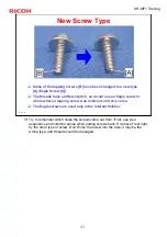
Page 63: ...ere a tapping screw was removed and vice versa The Eagle screws are used only in the internal finisher New Screw Type Try to remember which holes the screws came out from If not use your experience and common sense when putting screws back If it doesn t feel right try the other type of screw Don t force the screw into the hole it may be the wrong type and threads could be damaged ...

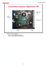
Page 64: ...SH MF1 Training 64 Slide 64 Component Location Right Cover Off PSU fan 2 PSU RFID board Main unit fan HVPP PSU Power supply unit HVPP High voltage power pack RFID Radio frequency identification ...

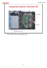
Page 65: ...SH MF1 Training 65 Slide 65 Component Location Left Cover Off AIO fan BICU Controller box CTL BICU Base Engine and Image Control Unit ...

Page 66: ...OMs from the old BICU and install them on the new one Make sure the EEPROM units are oriented correctly The notches must be oriented as shown in the illustrations on the next slide Enter the S N with SP5811 4 Do not change the DIP switches Refer to the FSM for the detailed BICU replacement procedure No additional notes ...

Page 67: ...wer EEPROM FRAM1 Notch Notch Insert the EEPROMs in the proper positions and make sure they are oriented correctly If replacing the EEPROMs but not the BICU follow the procedure in the FSM On production machines the EEPROMs will be labeled FRAM0 and FRAM1 Don t mix them up ...

Page 68: ...opy EEPROM data to SD card with SP5 824 001 if possible Replace new EEPROM on the BICU board Make sure the EEPROMs are oriented correctly The notches must be oriented as shown in the illustration on the previous slide Copy the data from SD card to EEPROM with SP5 825 001 Refer to the FSM for the detailed BICU replacement procedure 9 Ask supervisor for details No additional notes ...

Page 69: ...SH MF1 Training 69 Slide 69 Replacing the BICU EEPROMs Data is Dead Make sure you have the SMC report factory setting that comes with machine Input the factory settings manually No additional notes ...

Page 70: ...the old controller and install them on the new one Make sure the NVRAM is oriented correctly The notch should be oriented as shown in the illustrations on the next slide Do not change the DIP switches The 45 cpm and 50 cpm machines have different controller boards Don t mix them up Refer to the FSM for the detailed controller replacement procedure No additional notes ...

Page 71: ... MF1 Training 71 Slide 71 Replacing the Controller 2 NVRAM Notch RAM DIMMs Interface rails Orient the NVRAM as shown Do not use the empty NVRAM socket Empty socket will be removed from production machines ...

Page 72: ...hes must be oriented as shown in the illustrations on the previous slide Copy the data from SD card to NVRAM with SP5 825 001 Refer to the FSM for the detailed Controller board replacement procedure 9 The value of Total counter is reset to 0 when NVRAM is replaced 9 When Encryption is ON please refer to the information RTB issued separately See notes below At the time of writing the latest informa...

Page 73: ...SH MF1 Training 73 Slide 73 Replacing the Controller NVRAM Data is Dead Make sure you have the SMC report factory setting that comes with machine Input the factory settings manually No additional notes ...

Page 74: ...SH MF1 Training 74 Slide 74 ARDF In this section you will study the mechanisms of the optional ARDF This is built into all models of the Z C1 series ...

Page 75: ...view Same as the ARDF for Z C1 Feed roller and friction pad system Mixed original length mode is not possible No original size sensors No fax stamp Contains a space for mounting the card reader as described earlier No additional notes ...

Page 76: ... Friction Pad 3 Feed Roller 4 Registration Gate 5 Original Set Sensor 6 Pick up Roller 7 Platen Cover 8 Inverter Roller 9 Junction Gate 10 Jam Removal Knob 11 Exit Roller 12 Inverter Sensor 13 Original Exposure Guide 14 Registration Sensor 15 Registration Roller No additional notes ...

Page 77: ...77 ARDF Electrical Component Layout 1 Inverter Solenoid 2 Registration Sensor 3 Inverter Sensor 4 Transport Motor 5 Feed Clutch 6 Original Set Sensor 7 Cover Sensor 8 Feed Motor 9 Cooling Fan 10 Drive Board No additional notes ...

Page 78: ...ive 1 The feed motor drives the pick up and feed rollers through the feed clutch Feed Motor Transport Motor Feed Clutch Pick up Roller Feed Roller Inverter Roller Transport Roller Registration Roller Exit Roller No additional notes ...

Page 79: ...SH MF1 Training 79 Slide 79 Drive 2 This diagram shows the layout of the pulleys and timing belts Feed Motor Transport Motor No additional notes ...

Page 80: ...s set in the feeder the stopper prevents the pages from entering the scanner When the pick up roller drops onto the top of the stack the stopper moves out of the way and the pick up roller feeds the top sheet of paper to the feed roller Stopper No additional notes ...

Page 81: ...SH MF1 Training 81 Slide 81 Separation The feed roller and friction pad make sure that only one sheet of paper goes into the scanner Friction Pad No additional notes ...

Page 82: ...raining 82 Slide 82 Original Transport and Exit Single sided Originals The feed motor and transport motor feed the original through the scanner Motor speed depends on the reproduction ratio No additional notes ...

Page 83: ...irst the front side of the original is scanned When the registration sensor detects the leading edge of the original the inverter solenoid opens the junction gate The original is then fed to the inverter table Registration Sensor Inverter Solenoid Junction Gate No additional notes ...

Page 84: ...ction gate solenoid switches off and the junction gate is closed When the original has been fed onto the inverter table the feed motor switches on in reverse The inverter roller and registration roller feed the original to the ADF exposure glass and the reverse side will be scanned Inverter Sensor Registration Sensor Inverter Roller No additional notes ...

Page 85: ...nd Exit Two sided Originals 3 The original is then sent to the inverter table again to be turned over This is done so that the duplex copies will be properly stacked front side down in the exit tray in the correct order Exit Tray No additional notes ...

Page 86: ...SH MF1 Training 86 Slide 86 ADF Motor Cooling The fan pulls in air to cool the motors Fan No additional notes ...

Page 87: ...SH MF1 Training 87 Slide 87 Scanner No additional notes ...

Page 88: ...ensors Because of this the copy display has changed and the user must be careful to select the correct paper size No coating on the exposure glass Additional measures to prevent dust from entering the optics No anti condensation heater even as an option No additional notes ...

Page 89: ...ght When the original is fed from the ARDF it is fed past the ARDF exposure glass 2 and to the original exit The original does not stay on the main exposure glass The 1st and 2nd scanners stay at their home positions 1 Scanner HP sensor 2 ADF exposure glass 3 2nd scanner 2nd carriage 4 LED array 5 1st scanner 1st carriage 6 Exposure glass 7 Sensor board unit SBU 8 Lens Block There isn t an anti co...

Page 90: ...e Glass Reflector Exposure Glass Mirror CCD LED Array Light Guide Reflector Exposure Glass Mirror Light emitting device White LED LED number 35 pcs Light emitting mechanism Light guide reflector Unit supplied as service parts LED unit Merits of LED compared with Xenon Lamp Life is long energy saving high speed warm up Demerits of LED Low amount of light ...

Page 91: ... change in the sub scan direction is done by changing the scanner motor speed In the main scan direction it is done by image processing on the BCU board You can adjust the magnification in the sub scan direction by changing the scanner motor speed with SP4 008 In this machine wires are used instead of timing belts These are more difficult to replace but copy quality is better less jitter Note that...

Page 92: ...scanner If the original size is different from the paper in the selected paper tray the customer must input the correct original size at the operation panel By default the original size is assumed to be the same as the selected paper tray There is no Auto Paper Size Detect mode No additional notes ...

Page 93: ...r width detection the SH MF1 cannot detect the original size This means that SH MF1 does not have the Auto Paper Select function Because of the above the user must input the original size at the start of every job Therefore the copy display is different from other models No additional notes ...

Page 94: ...s paper dust cannot be detected When dust is detected the scanning position is shifted in the sub scan direction An alert is displayed on the operation panel when dust reoccurs after that 4020 002 Dust Detection Level 0 lowest detection Level 8 highest detection level Level 4 is the default If the level is higher the detection level is higher dust is more likely to be detected 4020 003 Dust reject...

Page 95: ...lacement and Adjustment Exposure Lamps Do not touch the new lamp directly by hand Grease spots will cause poor scanning quality Note that the copy adjustments must be done after replacing the lens block scanner motor or scanner wires ...

Page 96: ...SH MF1 Training 96 Slide 96 DF Exposure Glass The blue mark must be at the rear right corner Blue Mark No additional notes ...

Page 97: ...ervice Part The ARDF exposure glass bracket assembly is available as a service part The ARDF exposure glass is attached to its bracket with double sided tape This tape prevents dust from getting into the scanner Double sided tape No additional notes ...

Page 98: ...SP4 010 Sub Mag Reg See Image Adjustment Scanning SP4 011 Main Scan Reg See Image Adjustment Scanning SP4 688 DF Density Adjustment Use this to adjust the density level if the ID of outputs made in the DF and Platen mode is different Note The SBU is not a separate service part It is included in the Lens Block Assembly and the entire assembly should be replaced No additional notes ...

Page 99: ...SH MF1 Training 99 Slide 99 Replacement and Adjustment When setting the platen cover it is necessary to have a 1 to 2 mm gap on the upper side and on the left side No additional notes ...

Page 100: ...er feed mechanisms for the main body tray 1 bypass tray will be described in this section The optional feed units will be dealt with in a later section In this section you will do the following Learn how the paper feed mechanisms are driven Learn how paper size is detected ...

Page 101: ...tection Remaining paper sensors paper end sensor Paper Size Detection Paper size switch Tray Capacity 550 sheets Tray Extension Available By pass Tray Paper Feed System Feed roller and friction pad Paper Lift Mechanism Cams and springs Paper Detection By pass tray paper sensor Paper Size Detection None Tray Capacity 100 sheets No additional notes ...

Page 102: ...on sensor 3 Upper relay rollers 4 By pass feed roller 5 By pass friction pad 6 Lower relay rollers 7 Tray feed roller 8 Friction pad 9 Paper tray Additional notes The friction pad cannot be adjusted The machine makes the paper buckle at the registration rollers to correct paper skew The paper buckle can be adjusted for each paper type with SP 1003 ...

Page 103: ...y to hold paper longer than A4 Letter size To use longer paper Release the two locks A Extend the tray B and close the locks Paper Sizes LG SEF 8 5 x 13 SEF 8 x 13 SEF 8 25 x 13 SEF Long A5 LEF SEF B5 SEF A4 SEF LT SEF Short default Possible Paper Sizes Tray Mode No additional notes ...

Page 104: ...t When the tray A is pushed into the machine the bottom plate B lifts as follows The slopes on the guide blocks C on the machine lift up the tray arms D The springs E between the tray arms and bottom plate lift the plate No additional notes ...

Page 105: ... thickness selector from the normal position right to thicker paper position left the tray arms move to the rear side a little bit As a result the spring tension of the tray arms is stronger than before changing the selector s position Normal position right for paper 105 g m2 or less 28 lb or less Thicker paper position left for paper more than 105 g m2 28 lb No additional notes ...

Page 106: ...h the paper feeding via gears and clutches Each clutch corresponds with a roller as follows Registration clutch B Registration roller b Paper feed clutch C Feed roller c Relay clutch D Upper relay roller d1 and lower relay roller d2 By pass feed clutch E By pass feed roller e No additional notes ...

Page 107: ...r board A detects the size of the paper in the paper tray Sliding the end fence B changes the position of the paper size actuator C Paper size detection occurs after the tray set switch D detects the paper tray See the paper size detection table on the next slide No additional notes ...

Page 108: ...FF LT SEF OFF OFF OFF LG SEF OFF OFF ON Custom size OFF ON OFF B5 SEF ON OFF ON A5 SEF OFF ON ON A4 SEF SN3 SN2 SN1 Size The paper size detection sensor board determines the paper size based on the switch combination as shown in the paper size detection table above No additional notes ...

Page 109: ...SH MF1 Training 109 Slide 109 Paper End Detection When there is no paper in the tray the feeler A falls into the cutout B in the bottom plate and the paper end sensor C comes on No additional notes ...

Page 110: ...ng paper sensor signals The signals from the sensors indicate whether there are 500 450 250 or 50 sheets remaining A Remaining paper sensor 1 B Remaining paper sensor 2 OFF ON 451 550 sheets 100 ON ON 251 450 sheets 90 ON OFF 51 250 sheets 50 OFF OFF 1 50 sheets 10 Sensor 2 Sensor 1 Amount of paper No additional notes ...

Page 111: ...C starts to feed paper to the registration roller D through the relay roller E The by pass feed roller shaft has two cams 1 2 These cams release the bottom plate to press the stack of paper against the by pass feed roller There is no width sensor To prevent bad effects from too much friction between the feed roller and friction pad the by pass feed roller contains a metal plate ...

Page 112: ...SH MF1 Training 112 Slide 112 Laser Exposure No additional notes ...

Page 113: ...ror reflect the beam from the LD unit to the synchronization detector Two laser beams The LD unit writes two lines at the same time LD safety shutter When the user opens the front cover the shutter closes and blocks the laser beam path After you replace the LD unit adjust its position see Replacement and Adjustment There is a thermistor next to the laser unit not shown that checks the temperature ...

Page 114: ...ic Power Control APC The LD driver on the LD drive board automatically controls power for the laser diodes The laser diode power is adjusted in the factory Never adjust the variable resistors on the LD unit in the field No additional notes ...

Page 115: ...ened Additional details A safety switch turns off when the front cover or the rear door is opened As a result the relay on the PSU cuts off the power supply 5V to the LD board The electric circuits go through the engine board This system prevents unexpected laser emission and ensures user safety and technician safety ...

Page 116: ...The laser shutter A provides back up to the safety switches previous slide Even if the switches do not work and power gets to the laser diodes B the laser shutter physically stops the laser beam when the front cover C is open No additional notes ...

Page 117: ...SH MF1 Training 117 Slide 117 All In One Cartridge AIO ...

Page 118: ...das Per toner Merits reduces metering blade wear extends the life of the development roller Demerit The margin for smudged image is decreased However there is no problem on actual usage Development roller Uses a larger circumference development roller Dual charge rollers To ensure the sufficient charging for the life of AIO the SH MF1 P1 machines use two charge rollers In high speed machines there...

Page 119: ...ning blade 10 Waste toner tank The AIO All In One cartridge combines toner toner supply mechanism development mechanism photoconductive drum charge mechanism development mechanism and drum cleaning mechanism in a single unit The limiting factor for AIOs is toner The initial AIO that comes with the machine makes about 6k copies prints The supply AIO makes about 25k copies prints ...

Page 120: ... s surface after image development and transfer The charge rollers are charged to 1550 V and they transfer 900 V to the drum Cleaning blade is composed of polyurethane Q Why two charge rollers A Even with the cleaning blade the charge rollers will slowly get dirty Design testing showed that two rollers are necessary to ensure sufficient charging for the life of the AIO under all environmental cond...

Page 121: ...s the latent image on the drum as it rotates past The high voltage supply applies the following 600V to the development roller 1550V to the charge rollers 110V to the supply roller 490V to the metering blade The development components drum development roller metering blade and supply roller are in contact no photoconductor gap nor doctor gap Relative peripheral velocities OPC 1 Development roller ...

Page 122: ...a low toner condition If the toner end sensor is activated ten times in a row the toner near end condition exists Toner End When the toner near end condition occurs the machine starts the toner end count Toner End is based on dot count After toner consumption equivalent to 1 250 A4 prints copies at 5 coverage the toner end condition is achieved See the detection mechanism on the next two slides No...

Page 123: ...ate The gap E in the shutter plate does not align with the hole F in the gear so light is reflected back to the toner end sensor G Toner near end There is low resistance to the rotation of the agitator The torsion spring H causes the gap of the shutter plate to align with the hole in the agitator gear Light is not reflected back to the sensor A B C D E F H Toner present Toner end detected G See ne...

Page 124: ...SH MF1 Training 124 Slide 124 Toner End Detection Mechanism 2 Agitator gear tab Shutter plate Torsion spring Agitator gear Gap of shutter plate and hole in gear aligned No additional notes ...

Page 125: ... amount of toner remaining in the toner tank The RFID chip is also used to detect whether the cartridge is installed The RFID chip transmits receives data to from the RFID board B RFID Radio Frequency Identification This small RFID is not just a tag It stores information that allows the AIO to be transferred to another machine Access the RFID data via SP7 931 1 to SP7 931 23 ...

Page 126: ...P 7 931 015 R Total Counter SP 7 931 014 Refill Flag SP 7 931 013 Toner End SP 7 931 012 Remaining Toner SP 7 931 011 Serial Number SP 7 931 010 EDP Code SP 7 931 009 Recycle Count SP 7 931 008 New AIO SP 7 931 007 Maintenance ID SP 7 931 006 Color ID SP 7 931 005 Class ID SP 7 931 004 Area ID SP 7 931 003 Brand ID SP 7 931 002 Version SP 7 931 001 Machine ID SP Number Stored Data No additional no...

Page 127: ...SH MF1 Training 127 Slide 127 Fusing No additional notes ...

Page 128: ...the paper After fusing the paper passes through the fusing exit rollers and the paper exit rollers to the output tray See the Paper Exit section The thermistor detects the temperature of the hot roller See the Fusing Temperature control slide The thermostat provides backup overheat protection If making duplex copies the junction gate directs to paper to the inverter mechanism rather than the exit ...

Page 129: ...SH MF1 Training 129 Slide 129 Fusing Drive The main motor A drives the hot roller B the fusing exit rollers C and the paper exit rollers D through a gear train No additional notes ...

Page 130: ...nt creasing If creasing occurs frequently in the fusing unit remove all three screws and slide the entrance guide to the right Replace the two end screws only Do not replace the middle screw This procedure allows paper to have more direct access to the point where the hot roller and the pressure roller meet No additional notes ...

Page 131: ... pressure with the envelope lever A Less pressure is needed for envelopes which are thicker than normal paper Raise the lever to reduce the pressure This prevents jams and wrinkling when printing on envelopes Lower the lever to return pressure to normal for all other print jobs Normally this lever should be down C D You may need to increase pressure if the customer complains of insufficient fusing...

Page 132: ...it the looped wire on the fusing unit connector contains a fuse A When power is switched on after installing a new fusing unit the engine board detects the fusing unit through the looped wire However the fuse opens very shortly afterwards Also see slide 51 No additional notes ...

Page 133: ...cess The soft start process prevents the room lights from flickering The lamp stays on until the thermistor detects the standby temperature Then the CPU maintains this temperature using on off control At the start of printing the CPU raises the fusing temperature to the printing temperature At the Reload temperature the user can start job input ...

Page 134: ... At this time SC543 will be generated If the thermistor overheat protection fails there are thermostats in series with the common ground line of the fusing lamp If the temperature of a thermostat becomes greater than approximately 175 C the thermostat opens removing power from the fusing lamp At this time the machine stops operation No additional notes ...

Page 135: ...SH MF1 Training 135 Slide 135 Paper Exit No additional notes ...

Page 136: ...tandard Model Paper Exit M052 The paper exit sensor A detects paper misfeeds When the paper overflow sensor B is activated the machine detects that the paper stack height limit has been reached and stops printing No additional notes ...

Page 137: ... selected or a received fax document is printed junction gate 1 A and junction gate 2 C open the paper path to the upper unit internal finisher or 1 bin unit The paper is transported to the internal finisher or 1 bin unit D via the relay roller B The relay sensor E detects paper misfeeds No additional notes ...

Page 138: ...SH MF1 Training 138 Slide 138 Duplex PURPOSE OF THE SECTION In this section you will Learn how paper is fed in duplex mode ...

Page 139: ...rs feeds the inverted paper back to the registration roller When both sides have been printed junction gate 1 directs the paper to the output tray 1 Duplex inverter roller 2 Junction gate 2 3 Junction gate 1 4 Duplex relay sensor 5 Duplex transport rollers 6 Duplex entrance sensor 7 Inverter sensor To print on the second side the two junction gates direct the paper to the inverter roller The duple...

Page 140: ...s 5 The duplex motor 9 drives the duplex transport rollers 8 The junction gate solenoids 4 7 control the junction gates 1 Duplex inverter motor 2 Duplex inverter rollers 3 Junction gate 2 4 Junction gate 2 solenoid 5 Relay roller 6 Main motor 7 Junction gate 1 solenoid 8 duplex transport rollers 9 Duplex motor 10 Junction gate 1 No additional notes ...

Page 141: ...and opens the paper path to the upper unit and duplex section Junction gate 2 solenoid C also moves junction gate 2 D and opens the duplex inverter path A sheet of paper is fed to the duplex inverter rollers F by the relay roller The duplex inverter rollers are driven counterclockwise by the duplex inverter motor E at this time No additional notes ...

Page 142: ... back and fed to the duplex path In the duplex path paper is transported by the duplex transport rollers D which are driven by the duplex motor E The paper arrives at the registration rollers with the reverse side up After an image is printed and fused on the reverse side the paper goes to the paper exit section or upper unit internal finisher or 1 bin unit No additional notes ...

Page 143: ...terleave method is used The illustration to the right shows how the paper travels through the machine during duplex copying The illustration below shows image printing sequence 2 3 2 1 1 3 1 3 2 1 2 For each sheet the second side image is printed first so that the sheets will be stacked in the proper order on the output tray ...

Page 144: ... 144 Slide 144 Optional Paper Feed Units M375 M376 This section will cover only the items that are unique to the paper tray units The components and feed mechanism are basically the same as for the standard paper tray ...

Page 145: ...ray each PFU holds 550 sheets of paper If installed on the floor the bottom PFU must be a TK1100 M376 unit Has casters The paper trays are almost exactly the same as the standard paper tray The only difference is that the front plate is slightly higher on the PFU trays Standard Tray PFU Tray No additional notes ...

Page 146: ... Component Layout 1 Paper end sensor 2 Remaining paper sensors 3 Transport sensor 4 Tray set switch 5 Paper size detection sensor 6 PFU motor 7 PFU board 8 Feed clutch 1 2 3 4 5 6 7 8 Components 3 6 7 and 8 are unique to the paper tray units ...

Page 147: ...ing 147 Slide 147 Paper Feed Drive The paper feed motor A drives the feed roller B via a timing belt gears and the feed clutch C The transport rollers D direct the paper to the main unit A C B D No additional notes ...

Page 148: ...ning 148 Slide 148 Internal Finisher M054 only In this section you will study the mechanisms of the internal finisher The finisher is built into the M054 model It is not available as an option for the other models ...

Page 149: ...s than 300 mm 50 sheets Paper length 300 mm or more 30 sheets Size of paper that can be stapled Width 182 0 mm to 216 0 mm Length 254 0 mm to 356 0 mm Weights of paper that can be stapled 52 to 90 g m2 Number of stapling positions 1 position Tray Capacity 250 sheets 80 g m2 No additional notes ...

Page 150: ...ering Roller 4 Paper trailing edge guide 5 Shift roller 6 Entrance sensor 7 Entrance roller 8 Stapler tray 9 Stapler 10 Staple tray paper sensor 11 Reverse roller 12 Jogger fence sensor 13 Pick up solenoid 14 Paper exit sensor 15 Paper sensor arm 16 Lower limit sensor 17 Tray lift motor 1 2 3 4 5 6 7 8 9 10 11 12 13 14 15 16 17 No additional notes ...

Page 151: ... motor 3 Interlock switch 4 Pick up solenoid 5 Paper sensor 6 Tray lower limit sensor 7 Tray lift motor 1 2 3 4 5 6 7 The interlock switch turns off when the internal finisher front cover is opened As a result the relay on the PSU cuts off the power supply to the internal finisher ...

Page 152: ...Slide 152 Component Layout 3 1 Paper exit sensor 2 Entrance sensor 3 Staple tray paper sensor 4 Jogger fence HP sensor 5 Jogger motor 6 Gathering roller HP sensor 7 Gathering roller motor 1 2 3 4 5 6 7 No additional notes ...

Page 153: ...SH MF1 Training 153 Slide 153 Component Layout 4 1 Transport motor 2 Paper exit motor 3 Shift roller HP sensor 4 Shift roller motor 5 Stapler motor 1 2 3 4 5 No additional notes ...

Page 154: ...raining 154 Slide 154 Drive Layout 1 Tray lift motor 2 Gathering roller motor 3 Exit guide plate motor 4 Shift roller motor 5 Transport motor 6 Jogger motor 7 Paper exit motor 1 2 3 4 5 6 7 No additional notes ...

Page 155: ...oller When the entrance sensor detects the leading edge of the paper the exit guide plate lowers the exit guide plate unit from its home position The paper exit roller feeds the paper through to the output tray Transport Motor Entrance Roller Shift Roller Paper Exit Motor Paper Exit Roller Exit Guide Plate Motor Entrance Sensor This shows paper feed without stapling ...

Page 156: ... stack by shifting alternately to the left and right The shift roller motor moves the shift roller from side to side The shift roller HP sensor detects when the shift roller is at the home position again Shift Roller Shift Roller Motor HP Sensor No additional notes ...

Page 157: ...r to reverse the paper into the staple tray The reverse roller aligns the paper in the staple tray The staple tray paper sensor detects the presence or absence of paper Paper Exit Motor Gathering Roller Motor Staple Tray Paper Sensor Gathering Roller Transport Motor Reverse Roller This shows how the machine reverse feeds the sheet of paper into the stapler ...

Page 158: ...SH MF1 Training 158 Slide 158 Stapling 2 The gathering roller motor raises the gathering roller Then the next sheet is fed into the finisher and reversed into the stapler tray No additional notes ...

Page 159: ...SH MF1 Training 159 Slide 159 Stapling 3 The jogger motor drives the jogger There is only one stapling position and no stapler rotation Jogger Motor Jogger Stapler No additional notes ...

Page 160: ...aining 160 Slide 160 Stapling 4 After stapling the exit guide plate roller drops onto the top of the stack The paper exit roller feeds out the stack Exit Guide Plate Roller Paper Exit Roller No additional notes ...

Page 161: ...e 161 Jogger Fence Fine Adjustment You can adjust the jogging position of the jogger fence with the following SPs from 1 0 mm to 1 0 mm A4 6132 003 B5 6132 005 Legal 6132 008 Letter 6132 009 Other 6132 012 No additional notes ...

Page 162: ...SH MF1 Training 162 Slide 162 Tray Full Detection 1 The paper sensor solenoid moves the actuator until it touches the top of the stack Solenoid Actuator No additional notes ...

Page 163: ...ects the actuator the tray lift motor lowers the end of the tray nearest the exit This makes room for more paper on the tray If the tray lower limit sensor is activated the tray cannot be lowered any more Lower Limit Sensor Tray Lift Motor Paper Sensor No additional notes ...

Page 164: ... 6137 002 Free Run 2 Staple mode 6137 003 Free Run 3 Packing mode Output tray descends to the lowest position 6137 004 Free Run 4 Not assigned You can also make a free run with dip switches SW101 Packing mode Output tray descends to the lowest position OFF ON OFF OFF Staple mode OFF OFF ON OFF Shift mode OFF OFF OFF ON Normal mode OFF OFF OFF OFF mode 4 3 2 1 No additional notes ...

Page 165: ...e finisher status with the LEDs on the finisher main board Finisher software malfunction ON Firmware update Blink irregular Error occurring Jam SC etc Blink per 0 4 s Normal operation Free run mode Blink per 1 0 s Machine power OFF OFF Status LED No additional notes ...

Page 166: ...ain Board Check the DIP switch SW100 on the old main board If the settings on the new main board are different from the old main board change the settings on the new board they must be the same as the settings on the old board No additional notes ...

Page 167: ...SH MF1 Training 167 Slide 167 One bin Tray M053 only No additional notes ...

Page 168: ...ide 168 1 Bin Tray Components The exit sensor monitors for paper jams The paper sensor checks for paper on the 1 Bin tray The LED lights when there is paper on the 1 Bin tray Exit sensor Paper sensor LED No additional notes ...

Page 169: ...SH MF1 Training 169 Slide 169 1 Bin Tray Drive The 1 Bin tray is driven by a timing belt from the main unit No additional notes ...

Page 170: ... Environmental Conservation Technology for Environmental Conservation Energy Saving Paper Saving This section explains the technology used in this machine for environmental conservation and the default settings of related functions ...

Page 171: ... productivity when printing out duplex double sided images 5 High speed duplex output Allows documentation to be managed digitally cutting down on paper consumption Improves machine productivity when printing out duplex double sided images 4 Paper saving features 3 IH QSU 2 Hybrid QSU Reduction of warm up time Energy saving Reduction of CO2 emissions 1 QSU SH MF1 SH P1 Description Environmental Te...

Page 172: ...warm up to the Ready condition This is made possible through the utilization of dual fusing lamp heating low fusing point toner a pressure roller with a sponge surface layer and a thin surface layer hot roller 2 Hybrid QSU This technology adds an additional circuit to conventional QSU Technology which allows the benefits of reduced energy consumption and reduced warm up time described above to be ...

Page 173: ...e benefits of reduced energy consumption and reduced warm up time to be extended to color machines 4 Paper saving features 1 The duplex double sided and Combine features reduce paper consumption 2 The Document Server and other electronic document management features reduce paper consumption by offering an electronic method for storing and managing important documents No additional notes ...

Page 174: ...ugh the utilization of the Duplex Interleaf and high speed Inverter Transport features 6 Ozone reduction design Greatly reduces the machine s ozone emissions to near zero levels by utilizing 1 A charge roller belt instead of a corona wire 2 An image transfer roller belt instead of a corona wire based transfer system No additional notes ...

Page 175: ...he conventional pulverization method This allows the toner to fuse at a lower temperature which reduces the impact on the environment and contributes to achieving even higher image quality than before PxP toner also has other benefits including a reduction in the amount of toner needed to develop the image as well as an approximate 35 reduction in CO2 emissions during the toner manufacturing proce...

Page 176: ...l laws and regulations as well as user requirements in each market in which the products are sold 2 Reduces the noise generated by the polygon mirror motor 9 Minimization of harmful substances 1 Products sold in the EU conform to the RoHS Directive 2 Products sold in China conform to China s version of the RoHS Directive 3 In addition Ricoh imposes strict internal standards for limiting the presen...

Page 177: ...g Enables effective use of resources by recycling reusing the toner left over on the drum surface after image transfer 12 Recycle friendly design To maximize the recycling ratio of machine and component materials as well as the ease of performing the recycling in the field machine sections and components are designed so that the recyclable parts can be separated out easily In addition components a...

Page 178: ... follows Warm up time 20 seconds Recovery time Energy Saver Mode 1 second Sleep Mode 20 seconds Through major reductions in warm up time and recovery time from energy saver modes Low power Sleep QSU Quick Start Up Technology has eliminated the traditional trade off between energy saving and convenience of speed ...

Page 179: ...p Mode Panel Off Timer 10 sec 240 min Timer Starts Auto Off Timer 1 240 min After 240 min from last job Plug In Time Energy Saving When the machine is not being used the machine enters energy saver mode to reduce the power consumption by turning off the LCD of the operation panel and lowering the fusing temperature The area shaded green in this diagram represents the amount of energy that is saved...

Page 180: ...f Auto Off timer or Panel Off timer and Energy Saver timer the machine goes immediately to Off mode when the Auto Off timer expires It skips the Panel Off and Energy Saver modes Example Panel off 1 minute Low power 15 minutes Auto Off 1 minute The machine goes to Off mode after 1 minute Panel Off and Low Power modes are not used We recommend that the default settings should be kept If the customer...

Page 181: ...181 2 Energy Saving 2 2 Energy Saver Mode Condition of LEDs Condition of LEDs on the operation panel On Off Off Off Sleep Mode On On On Panel off Mode Main Power LED Energy Saver LED Operation Switch LED Mode No additional notes ...

Page 182: ...s held down for a second The machine is still in the stand by ready condition but turns off the LCD of the operation panel The machine recovers to the ready condition if one of the following occurs The Energy Saver key is pressed An original is placed in the ARDF The ARDF is lifted The user touches the operation panel The front door is opened or closed The user sends a job to the MFP In some MFP m...

Page 183: ...mode when one of the following is done The auto off timer runs out after the last job The operation switch is pressed to turn the power off When the machine enters sleep mode no power is supplied to the printing engine and almost none to the controller Recovery time Less than 20 seconds No additional notes ...

Page 184: ...the job is completed the machine returns to sleep mode immediately Panel Off and Low Power modes are skipped Power Consumption Warm up Operation Mode Ready Mode Sleep Mode Plug In Time Panel Off Mode Data is received Warm up Operation Mode Sleep Mode This timing chart shows what happens if data is received while the machine is in sleep mode Power consumption during warm up may be much higher than ...

Page 185: ...s to sleep mode via ready and panel off modes when the auto off timer runs out or the operation switch is pressed This is the same as Off mode Power Consumption Warm up Operation Mode Ready Mode Sleep Mode Plug In Time Panel Off Mode Operation Switch is pressed Warm up Operation Mode Ready Mode Sleep Mode Panel Off Mode This timing chart shows what happens if the operation switch is pressed while ...

Page 186: ...y the machine 8941 001 Operating time 8941 002 Standby time 8941 003 Energy Save time 8941 004 Low power time 8941 005 Sleep mode time This should only be used as a reference value because the power consumption specifications are measured in a controlled environment with a constant power supply To get an exact measurement at the customers site a watt meter must be used to measure the actual energy...

Page 187: ...t and convert the result to hours 4 Power consumption figures for each model are acquired from Publication System of MSDS_ _PEI PRODUCT ENVIRONMENT INFORMATION database 2 Energy Saving 2 3 Energy Save Effectiveness 2 SH MF1 194 W SH MF1m 197 W SH MF1f 159 W Standby mode SH MF1 2 86 W SH MF1m 5 30 W SH MF1f 2 71 W Sleep mode Same as standby mode Energy Saver mode Panel Off SH MF1 862 W SH MF1m 891 ...

Page 188: ... 005 Sleep mode Time Sleep 15 36 Total 6 3 69 199 00 18 52 75111 74000 003 Energy Save Time Energy save panel off 6 24 199 00 31 38 308046 306163 002 Standby Time Stand by Ready 4 41 891 00 4 95 21386 21089 001 Operating Time Operating Power consumptio n KWH 3 x 4 1000 5 Power Consumption Spec W 4 Running time hour 2 1 60 3 Time at End min 2 Time at Start min 1 SP8941 Machine Status Mode condition...

Page 189: ...ving 3 1 Measuring the Paper Consumed 1 1 Duplex Reduce paper volume in half 1 2 1 2 2 Combine Reduce paper volume in half 3 Duplex Combine Using both features together can further reduce paper volume by 3 4 1 2 3 4 1 234 No additional notes ...

Page 190: ...ounter SP 8581 001 Single sided with duplex mode SP 8421 001 Double sided with duplex mode SP 8421 002 Book with with duplex mode SP 8421 003 Single sided with combine mode SP 8421 004 Duplex with combine mode SP 8421 005 The total counter counts all pages printed The duplex and combine counter counts all pages printed with duplex and combine mode No additional notes ...

Page 191: ...s in Single sided with combine mode Number of pages in Duplex with combine mode B c g h c Total counter SP 8581 001 pages d Single sided with duplex mode SP 8421 001 pages e Double sided with duplex mode SP 8421 002 pages f Book with with duplex mode SP 8421 003 pages g Single sided with combine mode SP 8421 004 pages h Duplex with combine mode SP 8421 005 pages In the above formula Sheet A sheet ...

Reviews: