5.System Maintenance
187
Exiting Service Mode
Press the Exit key on the touch-panel.
Service Mode Lock/Unlock
At locations where the machine contains sensitive data, the customer engineer cannot operate the machine until the
Administrator turns the service mode lock off. This function makes sure that work on the machine is always done with the
permission of the Administrator.
1.
If you cannot go into the SP mode, ask the Administrator to log in with the User Tool and then set "Service Mode
Lock" to OFF after he or she logs in:
User Tools > System Settings > Administrator Tools > Service Mode Lock > OFF
This unlocks the machine and lets you get access to all the SP codes.
The CE can service the machine and turn OFF then ON the machine power. It is not necessary to ask the
Administrator to log in again each time the main power is turned ON.
2.
Go into the SP mode and set SP5-169 to "1" if you must use the printer bit switches.
3.
After machine servicing is completed:
Change SP5-169 from "1" to "0".
Turn OFF then ON the machine power. Tell the administrator that you have completed servicing the machine.
The Administrator will then set the "Service Mode Lock" to ON.
PM Counter/ Firmware Update
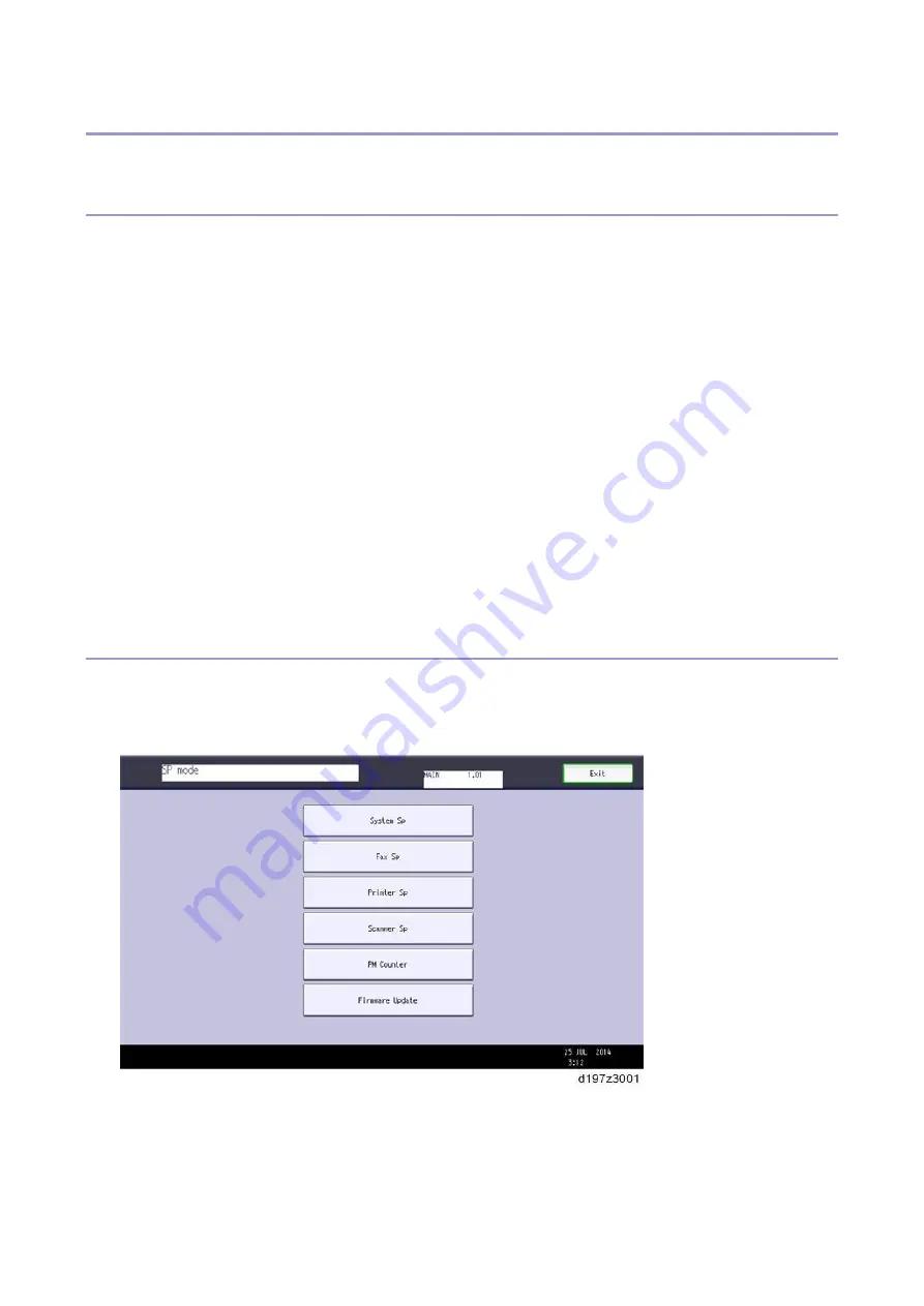
PM Counter and Firmware Update can be entered in the SP mode main screen.
PM Counter: PM counters for each PM part
Firmware Update: Immediate remote update and remote update at next visit
How to Check the PM Counter
Summary of Contents for M0A0
Page 2: ......
Page 10: ...8 ...
Page 12: ......
Page 34: ...2 Installation 22 9 Enter the password 10 Press OK 11 Enter the password again ...
Page 85: ...2 Installation 73 ...
Page 189: ...4 Replacement and Adjustment 177 ...
Page 203: ...5 System Maintenance 191 SP Mode Tables See Appendices ...
Page 229: ...5 System Maintenance 217 LDAP authorization information ...
Page 344: ...7 Detailed Descriptions 332 side guides from side to side ...
Page 358: ...7 Detailed Descriptions 346 ...
Page 368: ......
Page 558: ......
Page 574: ...1 Replacement and Adjustment 16 7 LCD A 4 8 Microphone A cushioning 1 ...
Page 622: ......
Page 624: ... A Short Edge Feed SEF B Long Edge Feed LEF ...
Page 626: ......
Page 632: ...1 Installation 6 ...
Page 752: ...5 Detailed Section Descriptions 126 Report Sample ...
Page 758: ...6 Specifications 132 Fax Unit Configuration Component No Remarks FCU 1 Speaker 2 ...
Page 760: ......
Page 762: ......
Page 776: ...2 Replacement and Adjustment 14 4 Detach the paper size switch from the bracket A Hook x2 ...

