6.Troubleshooting
251
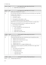
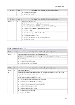
SC No.
Level
Error Name/Error Condition/Major Cause/Solution
SC542-
02
A
Fusing lamp (Center) not reloaded (Broken heater wire)
The heater (Center) thermistor does not reach the reload temperature 23 seconds after the start
of motor rotation.
The overtemperature prevention mechanism started working
Clear the SP: fusing SC.
Replace the thermistor.
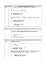
SC No.
Level
Error Name/Error Condition/Major Cause/Solution
SC543-00
A
Fusing (Center) thermopile high-temperature detected (software)
The temperature is detected to stay at 250 degrees C or higher for one second.
Shorted triac
Failure in the BiCU
Clear the SP: fusing SC.
Replace the BiCU.
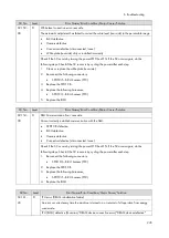
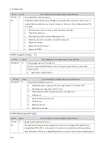
SC No.
Level
Error Name/Error Condition/Major Cause/Solution
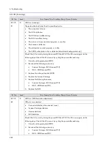
SC544-
00
A
Fusing (Center) thermopile high-temperature detected (hardware)
The hardware high-temperature error sensor flag is detected (250 degrees C or higher).
Damaged triac (shorted)
Failed engine control board
Failed fusing thermopile
Failed fusing thermistor
Abnormal fusing control software behavior
The PWM signal is continuously supplied from the IH inverter (due to a software or
temperature sensor error).
Clear the SP: fusing SC.
Replace the PSU.
Replace the Engine Board.
Replace the fusing thermopile.
Replace the fusing thermistor.
Replace the Fusing Unit.
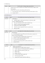
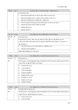
SC No.
Level
Error Name/Error Condition/Major Cause/Solution
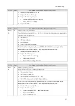
SC545-
00
A
Fusing (Center) lamp stays ON
The thermistor (center) has not detected the target temperature, even after the fusing lamp stays
ON for more than 11 seconds after reloading.
Deformed or floating thermistor
Summary of Contents for M0A0
Page 2: ......
Page 10: ...8 ...
Page 12: ......
Page 34: ...2 Installation 22 9 Enter the password 10 Press OK 11 Enter the password again ...
Page 85: ...2 Installation 73 ...
Page 189: ...4 Replacement and Adjustment 177 ...
Page 203: ...5 System Maintenance 191 SP Mode Tables See Appendices ...
Page 229: ...5 System Maintenance 217 LDAP authorization information ...
Page 344: ...7 Detailed Descriptions 332 side guides from side to side ...
Page 358: ...7 Detailed Descriptions 346 ...
Page 368: ......
Page 558: ......
Page 574: ...1 Replacement and Adjustment 16 7 LCD A 4 8 Microphone A cushioning 1 ...
Page 622: ......
Page 624: ... A Short Edge Feed SEF B Long Edge Feed LEF ...
Page 626: ......
Page 632: ...1 Installation 6 ...
Page 752: ...5 Detailed Section Descriptions 126 Report Sample ...
Page 758: ...6 Specifications 132 Fax Unit Configuration Component No Remarks FCU 1 Speaker 2 ...
Page 760: ......
Page 762: ......
Page 776: ...2 Replacement and Adjustment 14 4 Detach the paper size switch from the bracket A Hook x2 ...

