7.Detailed Descriptions
314
LED Head
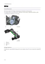
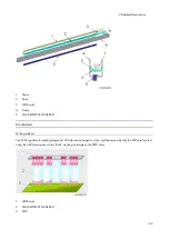
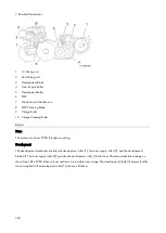
Each LED head has 26 LED chips on board, and each chip has a line of LEDs 8mm in length.
If a vertical line 8mm in width appears on the image parallel to the direction of paper feed, it may be caused
by a broken LED chip.
LED Positioning
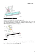
The LED head contacts the spacer on the drum in order to hold and adjust the correct focal distance from the PCDU
(slide-and-move method).
Image Position Adjustment
You can adjust the printing position from each tray with [Registration] in Menu.
At this time, the following controls are done as the adjustment in the machine;
Horizontal Scan: Adjusted by moving the whole image position.
Vertical Scan: Adjusted by changing the light-emission timing.
There is no mechanical adjustment, unlike laser writing.
Writing is applied across the extent of the LED head in the horizontal direction. So, if you want to adjust to
printing position to an area that is outside the one that is within the setting range in [Registration], adjust the
paper position in the feed tray.
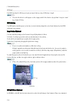
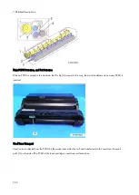
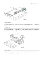
To adjust the paper position in the feed tray, you can adjust horizontal registration by loosening the screws on the
bottom of the tray, and then moving the holder to right or left (up to 2mm).
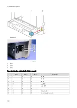
When at the default (±0) position, the holder position is the triangle marked area [A] in the picture below.
LED Light Volume Adjustment
An EEPROM on the LED head contains data which controls the light intensity of each element. There is no adjustment.
Summary of Contents for M0A0
Page 2: ......
Page 10: ...8 ...
Page 12: ......
Page 34: ...2 Installation 22 9 Enter the password 10 Press OK 11 Enter the password again ...
Page 85: ...2 Installation 73 ...
Page 189: ...4 Replacement and Adjustment 177 ...
Page 203: ...5 System Maintenance 191 SP Mode Tables See Appendices ...
Page 229: ...5 System Maintenance 217 LDAP authorization information ...
Page 344: ...7 Detailed Descriptions 332 side guides from side to side ...
Page 358: ...7 Detailed Descriptions 346 ...
Page 368: ......
Page 558: ......
Page 574: ...1 Replacement and Adjustment 16 7 LCD A 4 8 Microphone A cushioning 1 ...
Page 622: ......
Page 624: ... A Short Edge Feed SEF B Long Edge Feed LEF ...
Page 626: ......
Page 632: ...1 Installation 6 ...
Page 752: ...5 Detailed Section Descriptions 126 Report Sample ...
Page 758: ...6 Specifications 132 Fax Unit Configuration Component No Remarks FCU 1 Speaker 2 ...
Page 760: ......
Page 762: ......
Page 776: ...2 Replacement and Adjustment 14 4 Detach the paper size switch from the bracket A Hook x2 ...


