7.Detailed Descriptions
348
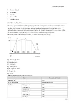
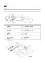
Name
Name
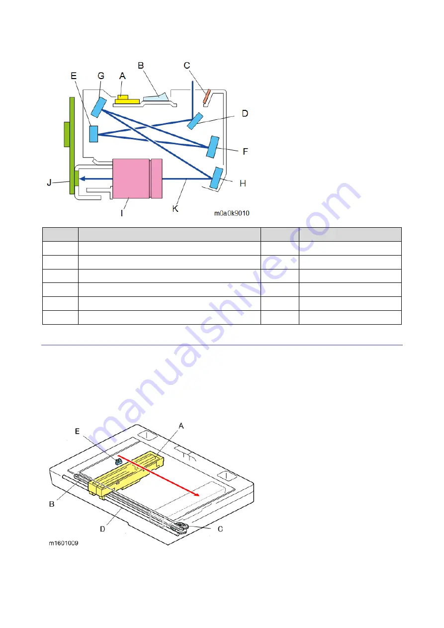
A
LED array board
G
4th mirror
B
Light Guiding Panel
H
5th mirror
C
Reflectors
I
Lens
D
1st mirror
J
CCD
E
2nd mirror
K
Light path
F
3rd mirror
Drive
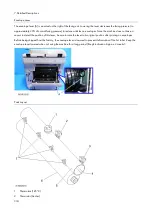
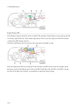
The scanner drive motor [C] drives the drive belt [B] in order to move the carriage [A] along the guide rod [D].
Scanning starts with the carriage [A] at the scanner HP sensor [E]. After scanning, the carriage [A] returns to the HP
sensor [E].
The actuator for the scanner HP sensor [E] is on the underside of the carriage [B].
When you wish to move the carriage, use the drive belt. Do not pull the carriage directly.
Summary of Contents for M0A0
Page 2: ......
Page 10: ...8 ...
Page 12: ......
Page 34: ...2 Installation 22 9 Enter the password 10 Press OK 11 Enter the password again ...
Page 85: ...2 Installation 73 ...
Page 189: ...4 Replacement and Adjustment 177 ...
Page 203: ...5 System Maintenance 191 SP Mode Tables See Appendices ...
Page 229: ...5 System Maintenance 217 LDAP authorization information ...
Page 344: ...7 Detailed Descriptions 332 side guides from side to side ...
Page 358: ...7 Detailed Descriptions 346 ...
Page 368: ......
Page 558: ......
Page 574: ...1 Replacement and Adjustment 16 7 LCD A 4 8 Microphone A cushioning 1 ...
Page 622: ......
Page 624: ... A Short Edge Feed SEF B Long Edge Feed LEF ...
Page 626: ......
Page 632: ...1 Installation 6 ...
Page 752: ...5 Detailed Section Descriptions 126 Report Sample ...
Page 758: ...6 Specifications 132 Fax Unit Configuration Component No Remarks FCU 1 Speaker 2 ...
Page 760: ......
Page 762: ......
Page 776: ...2 Replacement and Adjustment 14 4 Detach the paper size switch from the bracket A Hook x2 ...

