1.Replacement and Adjustment
10
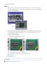
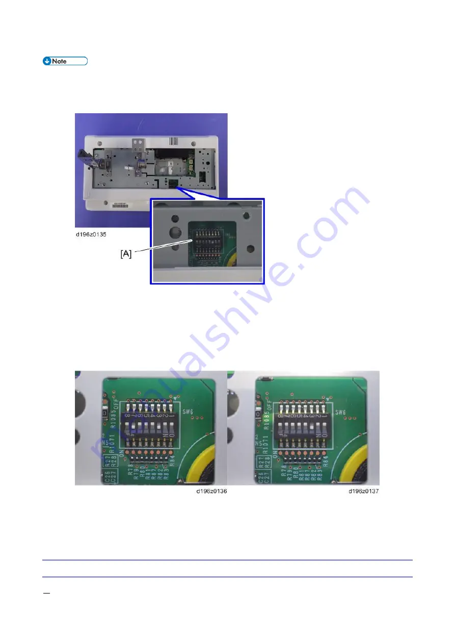
By factory default, switches No.3 and No.7 of the DIP switch [A] on the micro computer board are set to
ON. When installing the operation panel unit, make sure that the DIP switch setting is correct for the MFP on
which you are installing the panel.
The correct DIP switch setting depends on the MFP. Note the DIP switch settings of the old operation panel
unit before replacing, and apply the same settings to the new Smart Operation Panel. (Below are two
examples for DIP switch settings.)
When No.3 and No.7 are set to ON
This is the factory default setting of a service part
When only No.3 is set to ON
If the DIP switch setting is wrong, SC672 will be displayed.
After replacing the micro computer board, perform the following checks:
LED Check (
Key Check (
Wi-Fi Module
1.
Operation panel unit (
Summary of Contents for M0A0
Page 2: ......
Page 10: ...8 ...
Page 12: ......
Page 34: ...2 Installation 22 9 Enter the password 10 Press OK 11 Enter the password again ...
Page 85: ...2 Installation 73 ...
Page 189: ...4 Replacement and Adjustment 177 ...
Page 203: ...5 System Maintenance 191 SP Mode Tables See Appendices ...
Page 229: ...5 System Maintenance 217 LDAP authorization information ...
Page 344: ...7 Detailed Descriptions 332 side guides from side to side ...
Page 358: ...7 Detailed Descriptions 346 ...
Page 368: ......
Page 558: ......
Page 574: ...1 Replacement and Adjustment 16 7 LCD A 4 8 Microphone A cushioning 1 ...
Page 622: ......
Page 624: ... A Short Edge Feed SEF B Long Edge Feed LEF ...
Page 626: ......
Page 632: ...1 Installation 6 ...
Page 752: ...5 Detailed Section Descriptions 126 Report Sample ...
Page 758: ...6 Specifications 132 Fax Unit Configuration Component No Remarks FCU 1 Speaker 2 ...
Page 760: ......
Page 762: ......
Page 776: ...2 Replacement and Adjustment 14 4 Detach the paper size switch from the bracket A Hook x2 ...


