2.Installation
52
3.
Make sure that "Admin. Authentication" is ON.
User Tools > Machine Features > System Settings > Administrator Tools > Administrator Authentication
Management > Admin. Authentication
If this setting is OFF, ask the customer to change the setting to ON before you perform the installation procedure.
4.
Make sure that "Administrator Tools" is enabled (selected).
User Tools > Machine Features > System Settings > Administrator Tools >
Administrator Authentication Management> Available Settings
If this setting is disabled (not selected), ask the customer to enable (select) the setting before you perform the
installation procedure.
See the Operating Instructions (Security Guide) for the factory defaults.
Seal Check and Removal
Before opening the box (corrugated envelope), make sure that the seal has not been broken or peeled off. If the seal is
peeled off, it will leave a mark on the box.
If the seal has been broken or peeled off, even if only partially, this is considered an arrival defect.
You must check the box seals to make sure that they were not removed after the items were sealed in the box at the
factory before you do the installation.
1.
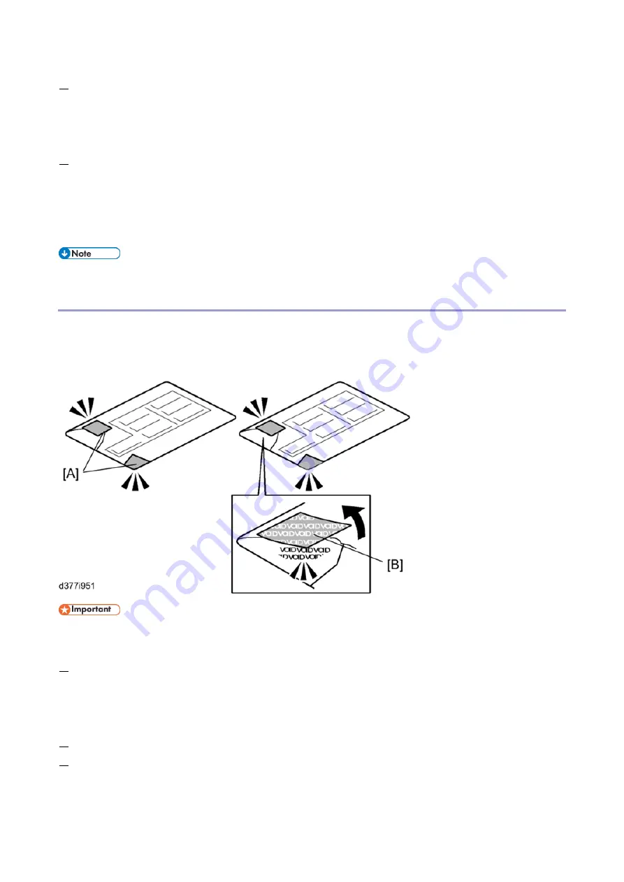
Check the box seals [A] on each corner of the box.
Make sure that a tape is affixed in each corner.
The surfaces of the tapes must be blank. If you see "VOID" on the tapes, do not install the components in the
box.
2.
If the surfaces of the tapes do not show "VOID", remove them from the corners of the box.
3.
When the seal is removed, you would see "VOID" marks [B]. In this condition, they cannot be attached to the box
again.
Summary of Contents for M0A0
Page 2: ......
Page 10: ...8 ...
Page 12: ......
Page 34: ...2 Installation 22 9 Enter the password 10 Press OK 11 Enter the password again ...
Page 85: ...2 Installation 73 ...
Page 189: ...4 Replacement and Adjustment 177 ...
Page 203: ...5 System Maintenance 191 SP Mode Tables See Appendices ...
Page 229: ...5 System Maintenance 217 LDAP authorization information ...
Page 344: ...7 Detailed Descriptions 332 side guides from side to side ...
Page 358: ...7 Detailed Descriptions 346 ...
Page 368: ......
Page 558: ......
Page 574: ...1 Replacement and Adjustment 16 7 LCD A 4 8 Microphone A cushioning 1 ...
Page 622: ......
Page 624: ... A Short Edge Feed SEF B Long Edge Feed LEF ...
Page 626: ......
Page 632: ...1 Installation 6 ...
Page 752: ...5 Detailed Section Descriptions 126 Report Sample ...
Page 758: ...6 Specifications 132 Fax Unit Configuration Component No Remarks FCU 1 Speaker 2 ...
Page 760: ......
Page 762: ......
Page 776: ...2 Replacement and Adjustment 14 4 Detach the paper size switch from the bracket A Hook x2 ...


