4.Service Tables
41
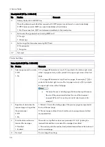
The four-digit hexadecimal value (N) after "L" indicates the RX level.
The high byte is given first, followed by the low byte. Divide the decimal value of N by -16 to get the RX level.
In the above example, the decimal value of N (= 0100 [H]) is 256.
So, the actual RX level is 256/-16 = -16 dB
3
Not used
Do not change this setting.
4
Line error mark print
0: OFF, 1: ON (print)
When "1" is selected, a line error mark is printed on the printout if a line error
occurs during reception. This shows error locations when ECM is turned off.
5
G3 communication parameter
display
0: Disabled
1: Enabled
This is a fault-finding aid. The LCD shows the key parameters (see "G3
Communication Parameters" below this table). This is normally disabled
because it cancels the CSI display for the user.
Be sure to reset this bit to "0" after testing.
6
Protocol dump list output after
each communication
0: Off
1: On
This is only used for communication troubleshooting. It shows the content of
the transmitted facsimile protocol signals. Always reset this bit to 0 after
finishing testing.
If system switch 09 bit 6 is at "1", the list is only printed if there was an error
during the communication.
7
Not used
Do not change the setting.
G3 Communication Parameters
Modem rate
336: 33600 bps 168: 16800 bps
312: 31200 bps 144: 14400 bps
288: 28800 bps 120: 12000 bps
264: 26400 bps 96: 9600 bps
240: 24000 bps 72: 7200 bps
216: 21600 bps 48: 4800 bps
192: 19200 bps 24: 2400 bps
Resolution
S: Standard (8 x 3.85 dots/mm)
D: Detail (8 x 7.7 dots/mm)
F: Fine (8 x 15.4 dots/mm)
SF: Superfine (16 x 15.4 dots/mm)
21: Standard (200 x 100 dpi)
22: Detail (200 x 200 dpi)
44: Superfine (400 x 400 dpi)
Compression mode
MMR: MMR compression
MR: MR compression
MH: MH compression
JBO: JBIG compression (Optional mode)
JBB: JBIG compression (Basic mode)
Communication mode
ECM: With ECM
Summary of Contents for M0A0
Page 2: ......
Page 10: ...8 ...
Page 12: ......
Page 34: ...2 Installation 22 9 Enter the password 10 Press OK 11 Enter the password again ...
Page 85: ...2 Installation 73 ...
Page 189: ...4 Replacement and Adjustment 177 ...
Page 203: ...5 System Maintenance 191 SP Mode Tables See Appendices ...
Page 229: ...5 System Maintenance 217 LDAP authorization information ...
Page 344: ...7 Detailed Descriptions 332 side guides from side to side ...
Page 358: ...7 Detailed Descriptions 346 ...
Page 368: ......
Page 558: ......
Page 574: ...1 Replacement and Adjustment 16 7 LCD A 4 8 Microphone A cushioning 1 ...
Page 622: ......
Page 624: ... A Short Edge Feed SEF B Long Edge Feed LEF ...
Page 626: ......
Page 632: ...1 Installation 6 ...
Page 752: ...5 Detailed Section Descriptions 126 Report Sample ...
Page 758: ...6 Specifications 132 Fax Unit Configuration Component No Remarks FCU 1 Speaker 2 ...
Page 760: ......
Page 762: ......
Page 776: ...2 Replacement and Adjustment 14 4 Detach the paper size switch from the bracket A Hook x2 ...


