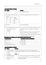
4.Service Tables
71
output
0: Off
1: On (Forbid
output)
7
Not used
Do not change this setting.
G3 Switch 02 (SP No. 1-105-003)
No Function
Comments
0
G3 protocol mode
used
0: Standard and non-
standard
1: Standard only
Change this bit to 1 only when the other end can only communicate with machines
that send T.30-standard frames only.
1: Disables NSF/NSS signals (these are used in non-standard mode
communication)
1-
6
Not used
Do not change the settings.
7
Short preamble
0: Disabled 1: Enabled
Refer to Appendix B in the Group 3 Facsimile Manual for details about Short
Preamble.
G3 Switch 03 (SP No. 1-105-004)
No Function
Comments
0
DIS detection number
(Echo countermeasure)
0: 1
1: 2
0: The machine will hang up if it receives the same DIS frame twice.
1: Before sending DCS, the machine will wait for the second DIS which is
caused by echo on the line.
1
Not Used
Do not change the settings.
2
Not Used
Do not change the settings.
3
ECM frame size
0: 256 bytes
1: 64 bytes
Keep this bit at "0" in most cases.
4
CTC transmission conditions
0: After one PPR signal received
1: After four PPR signals
received (ITU-T standard)
0: When using ECM in non-standard (NSF/NSS) mode, the machine sends
a CTC to drop back the modem rate after receiving a PPR, if the following
condition is met in communications at 14.4, 12.0, 9.6, and 7.2 kbps.
NTransmit- Number of transmitted frames
NResend- Number of frames to be retransmitted
1: When using ECM, the machine sends a CTC to drop back the modem
rate after receiving four PPRs.
Summary of Contents for M0A0
Page 2: ......
Page 10: ...8 ...
Page 12: ......
Page 34: ...2 Installation 22 9 Enter the password 10 Press OK 11 Enter the password again ...
Page 85: ...2 Installation 73 ...
Page 189: ...4 Replacement and Adjustment 177 ...
Page 203: ...5 System Maintenance 191 SP Mode Tables See Appendices ...
Page 229: ...5 System Maintenance 217 LDAP authorization information ...
Page 344: ...7 Detailed Descriptions 332 side guides from side to side ...
Page 358: ...7 Detailed Descriptions 346 ...
Page 368: ......
Page 558: ......
Page 574: ...1 Replacement and Adjustment 16 7 LCD A 4 8 Microphone A cushioning 1 ...
Page 622: ......
Page 624: ... A Short Edge Feed SEF B Long Edge Feed LEF ...
Page 626: ......
Page 632: ...1 Installation 6 ...
Page 752: ...5 Detailed Section Descriptions 126 Report Sample ...
Page 758: ...6 Specifications 132 Fax Unit Configuration Component No Remarks FCU 1 Speaker 2 ...
Page 760: ......
Page 762: ......
Page 776: ...2 Replacement and Adjustment 14 4 Detach the paper size switch from the bracket A Hook x2 ...


