background image

Items

Values

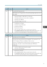
• Front Cover
• Main Motor Lock
• Polygon Motor Lock
• Fan Lock
• LD XDETP Check
• LD Error
• HVP Error
• Fuser High Temp
• Register Sens.
• Exit Sens.

0: Off
1: On

• Fuser Thermistor
• Video Thermistor

0x00 to 0xFFFF

• AIO ID Chip
• AC Low Voltage
• Plate Sensor

0: Off
1: On

Output Check

4. System Maintenance

60

Summary of Contents for M0AE-17

Page 1: ...Model Rev P1 MF1 Machine Codes SFP M290 M0AF MFP M291 M0AE Field Service Manual January 2016 ...

Page 2: ......

Page 3: ...r other property Obey these guidelines to avoid problems such as misfeeds damage to originals loss of valuable data and to prevent damage to the machine This information provides tips and advice about how to best service the machine General Safety Instructions For your safety please read this manual carefully before you use this product Keep this manual handy for future reference Safety Informatio...

Page 4: ...achine Personnel moving or working around the machine should always wear proper clothing and footwear Never wear loose fitting clothing or accessories neckties loose sweaters bracelets etc or casual footwear slippers sandals etc when lifting or moving the machine Always unplug the power cord from the power source before you move the machine Before you move the product arrange the power cord so it ...

Page 5: ...rs to lubricate moving parts while the machine is operating Special Tools Use only standard tools approved for machine maintenance For special adjustments use only the special tools and lubricants described in the service manual Using tools incorrectly or using tools that could damage parts could damage the machine or cause injuries During Maintenance General Before you begin a maintenance procedu...

Page 6: ...s leading to hand or leg injuries Use dry rags to soak up spills Power Plug and Power Cord Before servicing the machine especially when responding to a service call always make sure that the power plug has been inserted completely into the power source A partially inserted plug could lead to heat generation due to a power surge caused by high resistance and cause a fire or other problems Always ch...

Page 7: ...e Return used drums to the service center for handling in accordance with company policy regarding the recycling or disposal of such items Points to Confirm with Operators At the end of installation or a service call instruct the user about use of the machine Emphasize the following points Show operators how to remove jammed paper and troubleshoot other minor problems by following the procedures d...

Page 8: ...er If there are signs of any problem seek medical attention If toner spills on clothing wash the affected area immediately with soap and cold water Never use hot water Hot water can cause toner to set and permanently stain fabric Handling and Storing Toner Toner used toner and developer are extremely flammable Never store toner developer toner cartridges or toner bottles including empty toner bott...

Page 9: ... should be near the machine and easily accessible 3 Note that some components of the machine and the paper tray unit are supplied with electrical voltage even if the main power switch is turned off 4 If any adjustment or operation check has to be made with exterior covers off or open while the main switch is turned on keep hands away from electrified or mechanically driven components 5 If the Star...

Page 10: ...nly when exposed to an open flame 2 Dispose of used toner developer and organic photoconductors in accordance with local regulations These are non toxic supplies 3 Dispose of replaced parts in accordance with local regulations 4 When keeping used lithium batteries in order to dispose of them later do not put more than 100 batteries per sealed box Storing larger numbers or not sealing them apart ma...

Page 11: ... Turn off the main switch before attempting any of the procedures in the Laser Unit section Laser beams can seriously damage your eyes RoHS Compliance These machines are fully compliant with Chinese RoHS and contain no restricted materials such as lead mercury cadmium hexavalent chrome polybrominated biphenyl or polybrominated diphenyl ether 9 ...

Page 12: ...s This manual uses several symbols and abbreviations The meaning of those symbols and abbreviations are as follows Clip ring Screw Connector Clamp E ring C ring Spring Timing Belt FFC Paper Feed SEF LEF The notations SEF and LEF describe the direction of paper feed The arrows indicate the direction of paper feed 10 ...

Page 13: ...llowed by Adjust Other Settings and then select 1 for Destination Code Trademarks Microsoft and Windows are registered trademarks of Microsoft Corporation in the United States and or other countries PostScript is a registered trademark of Adobe Systems Incorporated PCL is a registered trademark of Hewlett Packard Company Ethernet is a registered trademark of Xerox Corporation Wi Fi is a registered...

Page 14: ...rganic Cleaners 4 Power Plug and Power Cord 4 After Maintenance 5 Disposal of Used Items 5 Points to Confirm with Operators 5 Special Safety Instructions for Toner 6 Accidental Physical Exposure 6 Handling and Storing Toner 6 Toner Disposal 7 Safety Instructions for the Machine 7 Prevention of Physical Injury 7 Health Safety Conditions 7 Observance of Electrical Safety Standards 8 Safety and Ecolo...

Page 15: ...t Points to Remember 19 General Configuration 19 Product Overview 20 Paper Path and Image Writing 20 Drive Layout 21 2 Installation and Preventive Maintenance Installation and Preventive Maintenance 23 Installation 23 Preventive Maintenance 23 3 Replacement and Adjustment Before You Begin 25 Before You Begin 25 Special Tools 25 Printing the Configuration Page 25 Exterior Covers 26 AIO 26 Bottom Co...

Page 16: ...n 41 Fan 41 Fusing Unit 42 Fusing Unit 42 Electrical Components 43 Main Board 43 Main Board of SFP Models 43 Main Board of MFP Models 44 Wi Fi PCB Wi Fi Models Only 45 PSU 45 HVP 46 Scanner 48 Scanner Unit 48 Scanner Open Close Switch 50 Sensors 51 Registration Sensor 51 Exit Sensor 51 Thermistor 51 Bottom Plate Position Sensor 52 Paper Size Sensor 52 4 System Maintenance Utilities 55 Using CE Too...

Page 17: ...ndicators and Error Status 63 Points to Note 63 Fatal SC Codes Fusing Related Errors 64 Executing Fusing SC Reset 64 SC Tables 65 SC Table Key 65 SC2xx Polygon Motor Errors 66 SC4xx Bias Leak 68 SC5xx Main Motor Errors Fusing Errors 69 SC6xx Communication Errors 74 SC10xx Others 74 Image Problems 75 Overview 75 Dark Lines in Halftone Areas 76 6 Energy Saving Energy Save 77 Energy Saving Modes 77 1...

Page 18: ...16 ...

Page 19: ...r details about machine specifications see the user guide Software Specifications For details about system requirements for drivers see the user guide For details about system requirements for the Virtual Operation Panel see the manual for the Virtual Operation Panel 17 ...

Page 20: ...11b g n Comparison of SFP and MFP Models Abbrev PPM Print Scan Copy ADF Operation Panel SFP 22 YES NO NO NO 1 MFP 22 YES YES YES NO 2 1 The SFP has two LEDs to indicate status and errors 2 The MFP has a Start button and two LEDs to indicate status and errors Feature Summary Feature SFP MFP Weight For details see the user guide Tray capacity GDI driver Available Available TWAIN driver Not Available...

Page 21: ...ssage is displayed on the Virtual Operation Panel Printing cannot be continued until the waste toner box is replaced If Waste Toner Full is detected during printing printing will continue until the end of that job Important Points to Remember Virtual Operation Panel Use the Virtual Operation Panel to configure settings view the status copy MFP only and scan MFP only For details see the manual for ...

Page 22: ...ration Sensor 2 Polygon Mirror 10 Drum 3 Paper Size Sensor 11 Image Transfer Roller 4 Paper Tray 12 Hot Roller 5 Bottom Plate Position Sensor 13 Pressure Roller 6 Paper Feed Roller 14 Paper Exit Roller 7 Registration Roller 15 Exit Sensor 8 Paper Transport Roller 1 Product Information 20 ...

Page 23: ...Name No Name 1 Paper Feed Clutch 6 Drum inside the AIO 2 Main Motor 7 Paper Transport Roller 3 Paper Exit Roller 8 Paper Feed Roller 4 Pressure Roller 9 Bottom Plate Lift Clutch 5 Hot Roller New Product Information 21 ...

Page 24: ...1 Product Information 22 ...

Page 25: ...e Maintenance This product can be installed and maintained by the user Installation For details about the installation requirements and installation procedures see the user guide Preventive Maintenance For details about how to maintain the machine see the user guide 23 ...

Page 26: ...2 Installation and Preventive Maintenance 24 ...

Page 27: ... at least 10 minutes Avoid touching the components inside the machine that are labeled as hot surfaces Special Tools There are no special tools required for disassembling the machine However you must have these items Standard length hex screwdriver Stubby hex screwdriver Thin radio pliers Printing the Configuration Page To print the Configuration Page press the Power button 3 times rapidly within ...

Page 28: ...Exterior Covers AIO 1 Open the top cover 2 Remove the AIO A Bottom Cover 1 Open the top cover 2 Remove the small cover A x1 3 Replacement and Adjustment 26 ...

Page 29: ... upside down 5 Remove the small cover A x1 6 Remove the screws on the bottom cover x6 7 Remove the bottom cover The bottom cover has hooks on the inside Gently loosen the cover from the hooks by using the tip of a small screwdriver Exterior Covers 27 ...

Page 30: ...ing the bottom cover place a mat underneath the machine to prevent damage to the HVP and PCB A when placing the machine with its bottom side down Top Cover SFP 1 Open the top cover A 3 Replacement and Adjustment 28 ...

Page 31: ...2 Remove the guide rail B x1 3 Disconnect the laser unit A from the top cover x5 4 Remove the top cover A Exterior Covers 29 ...

Page 32: ...5 Remove the paper feed guide A MFP The MFP does not have a top cover For details on how to remove the scanner unit see page 48 Scanner Unit 3 Replacement and Adjustment 30 ...

Page 33: ...r and page 43 Electrical Components After Replacing the Laser Unit After replacing the laser unit check the position of the image area on the page and adjust the registration value if necessary The registration value can be adjusted using either one of the following Virtual Operation Panel CE Tools Laser Unit 31 ...

Page 34: ...r Feed Roller 1 Remove the bottom cover page 26 2 Remove the main motor page 38 3 Remove the feed guide A x 4 4 Slide the paper feed roller A to the right and remove it x 2 bushing x 2 3 Replacement and Adjustment 32 ...

Page 35: ...and remove the paper feed roller A from the shaft Friction Pad 1 Remove the bottom cover page 26 2 Remove the gear A x 1 3 Remove the friction pad unit B x3 4 Release the 2 hooks 5 Remove the friction pad A Paper Feed 33 ...

Page 36: ...AIO page 26 2 Push down the rear end of the bushing A on the right end of the registration roller B to unlock the roller 3 Remove the registration roller B Image Transfer Roller 1 Remove the AIO page 26 3 Replacement and Adjustment 34 ...

Page 37: ...2 Remove the image transfer roller with the bushing A 3 Remove the gear x 1 bushing x 2 spring x 2 from the image transfer roller A Paper Feed 35 ...

Page 38: ...move the bottom cover page 26 2 Remove the main motor page 38 3 Remove the gear A 4 Remove the paper feed clutch A and the gear B x1 Bottom Plate Lift Clutch 1 Remove the bottom cover page 26 3 Replacement and Adjustment 36 ...

Page 39: ...2 Disconnect the harness 3 Remove the friction pad unit A x3 Remove the bottom plate lift clutch B x1 Paper Feed 37 ...

Page 40: ...r A x1 Remember the position of the gear A Put the gear back in the correct position after replacing the motor 4 Remove the gear A Remove the bracket B 3 Remember the position of the gear A Put the gear back in the correct position after replacing the motor 3 Replacement and Adjustment 38 ...

Page 41: ...5 Remove the T shaped stopper A Remember the position of the T shaped stopper A Put the stopper back in the correct position after replacing the motor 6 Remove the bracket A 2 2 Drive 39 ...

Page 42: ...7 Remove the main motor A with its bracket 3 8 Remove the gears A B and C 1 9 Remove the bracket A from the main motor B 3 3 Replacement and Adjustment 40 ...

Page 43: ...Remove the bottom cover page 26 2 Remove the Wi Fi PCB Wi Fi models only page 45 3 Remove the bracket A 1 4 Remove the fan A 1 1 When replacing the fan make sure that the decal on the fan faces the outside Fan 41 ...

Page 44: ...ge 26 2 Remove the Wi Fi PCB Wi Fi Models only page 45 3 Remove the fan page 41 4 Remove the PSU page 45 5 Remove the main motor with its bracket page 38 6 Disconnect the harness A on the PCB 7 Remove the fusing unit A x4 3 Replacement and Adjustment 42 ...

Page 45: ...ce with double sided tape Before replacing the main board print the Configuration page by pressing the Power button 3 times rapidly The EEPROM cannot be removed Before replacing the main board remember the machine s PNP ID Destination Code and Serial No After replacing the main board enter them manually by using CE Tools For details refer to page 55 Using CE Tools Main Board of SFP Models 1 Remove...

Page 46: ...Main Board of MFP Models 1 Remove the bottom cover page 26 2 Remove the main board A x4 x14 x1 3 Replacement and Adjustment 44 ...

Page 47: ...Wi Fi PCB Wi Fi Models Only 1 Remove the bottom cover page 26 2 Remove the Wi Fi PCB A x2 x1 hook x1 PSU 1 Remove the bottom cover page 26 2 Remove the bracket A 3 Electrical Components 45 ...

Page 48: ...hen removing the PSU keep the harness B away from the heat sink C Otherwise the cover of the harness may melt because of the heat 4 Remove the PSU B from the bracket A x4 HVP 1 Remove the bottom cover page 26 3 Replacement and Adjustment 46 ...

Page 49: ...2 Remove the HVP A x4 x1 Electrical Components 47 ...

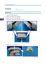
Page 50: ...move the AIO page 26 2 Remove the bottom cover page 26 3 Remove the main board page 43 4 Release the guides of the paper feed tray A 5 Remove the paper feed guide A 3 Replacement and Adjustment 48 RTB 4 This section was revised ...

Page 51: ... A release the right linkage first 6 Remove the rear cover from the right hand side A 7 Open the scanner unit A and remove the guide rail B x1 8 Remove the scanner unit A 9 Remove the laser unit from the scanner unit A x4 Scanner 49 ...

Page 52: ...Scanner Open Close Switch 1 Remove the bottom cover page 26 2 Remove the sheet A 3 Remove the bracket B x1 4 Remove the scanner open close switch A x2 3 Replacement and Adjustment 50 ...

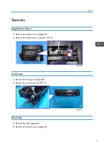
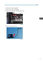
Page 53: ... 1 Remove the bottom cover page 26 2 Remove the registration sensor A x1 Exit Sensor 1 Remove the fusing unit page 42 2 Remove the exit sensor A x1 Thermistor 1 Remove the AIO page 26 2 Remove the bottom cover page 26 Sensors 51 ...

Page 54: ... x1 4 Remove the thermistor A x1 Bottom Plate Position Sensor 1 Remove the friction pad unit page 33 2 Remove the bottom plate position sensor A x1 Paper Size Sensor 1 Remove the AIO page 26 3 Replacement and Adjustment 52 ...

Page 55: ...2 Remove the top cover page 28 3 Remove the main board page 43 4 Remove the bracket A on the feed guide x2 5 Remove the paper size sensor Sensors 53 ...

Page 56: ...3 Replacement and Adjustment 54 ...

Page 57: ...t the PC is connected to the machine To start CE Tools click on the CE Tools icon To return to the default values click Set Default on each screen To update to the latest information click Refresh on each screen To apply the settings click Apply on each screen Adjust Registration 55 ...

Page 58: ...aper Thin Paper 40 to 40 0 1 mm steps Adjust the leading edge registration For User 2 to 2 1 mm steps 2 Side to Side Adjust the side to side registration By Pass Tray 40 to 40 0 1 mm steps Adjust the side to side registration For User 6 to 6 1 mm steps Adjust Temperature 4 System Maintenance 56 ...

Page 59: ...teps Adjust Other Settings No Item Details Values 1 Sub Scan Magnification Specify the sub scan magnification 8 to 8 0 1 steps 2 Transfer Roller Bias Adjust the transfer roller bias 10 to 10 12 steps 3 Image Density Adjust the image density 3 to 3 7 steps 4 PNP ID Specify the Plug and Play ID Normally do not change the PNP ID After replacing the main board return the PNP ID to its original value 0...

Page 60: ...s the error code for Fusing Unit Third Jam Error Fatal Error Specify whether to enable SC 559 detection 0 Off 1 On 7 Plate Control Mode Specify whether to use the plate control mode 0 On 2 Off 8 Low Humidity Mode Black lines a few millimeters thick may appear on prints when the machine is operated in a low humidity environment Enabling this mode may help to solve the problem 0 Off 1 On 9 Primary C...

Page 61: ...nge the serial number After replacing the main board return the serial number to its original value 13 Rom Ver The ROM version number is displayed 14 Total Counter Engine The total counter is displayed 0 to 99999999 15 2nd Serial No Do not change the 2nd Serial No Get Input Status Click Refresh to update the information The input status of the following items can be viewed Utilities 59 ...

Page 62: ...ygon Motor Lock Fan Lock LD XDETP Check LD Error HVP Error Fuser High Temp Register Sens Exit Sens 0 Off 1 On Fuser Thermistor Video Thermistor 0x00 to 0xFFFF AIO ID Chip AC Low Voltage Plate Sensor 0 Off 1 On Output Check 4 System Maintenance 60 ...

Page 63: ...or Feed Clutch Plate Clutch Fan High Speed Fan Low Speed LD Heater On LD1 LD2 Fuser Heater Charge Bias Develop Bias Trans Current Polygon Motor LD1 Heate On LD2 Heate On On Off FusingSCReset 0 Execute Data Upload Do not use Data Upload settings CIS Calibration Do not use CIS Calibration settings Utilities 61 ...

Page 64: ...Firmware Update For details on how to update the machine firmware refer to the firmware update guide 4 System Maintenance 62 ...

Page 65: ... user guide To find out the SC code see the message area on the Status screen of the Virtual Operation Panel Status Screen 1 The device status indicate Error 2 Error messages and SC codes are displayed in this area Points to Note All SC codes are logged When an error occurs turn the power OFF and then ON This usually solves the problem 63 ...

Page 66: ...Once a fatal error occurs the machine cannot be used until the problem has is solved When SC 559 Detection is enabled the machine will shut down after three consecutive fusing jam errors For safety this setting should remain enabled When a fatal error fusing related SC code occurs the machine cannot be operated until the service technician releases the error by selecting On for FusingSCReset After...

Page 67: ...ocedure A This is a fatal error The machine is disabled due to a problem in the fusing unit The operator cannot operate the machine The machine requires immediate servicing by a service technician After solving the problem FusingSCReset must be executed to release the machine for normal operation B Only the function that uses the defective unit is disabled The SC code is shown in the message on th...

Page 68: ...nnectors and then connect them again This is to make sure that the problem was not caused by a bad or loose connection SC2xx Polygon Motor Errors Code Level Details 202 D Polygon Motor On Timeout Error No lock signal was received within 10 sec after the polygon motor was turned on The polygon motor driver I F harness is loose broken or defective The polygon motor is broken or defective Cycle the p...

Page 69: ... I F harness Replace the polygon motor Replace the laser unit Code Level Details 204 D Polygon Motor Lock Signal Error Four samplings within 200 ms indicate that the polygon motor lock signal remained inactive beyond the prescribed number of revolutions The I F harness between the motor and driver board is loose broken or defective The driver board is defective The motor is defective Cycle the pow...

Page 70: ...s Replace the polygon motor Replace the laser unit Replace the main board SC4xx Bias Leak Code Level Details 491 D Bias Leak A bias leak has occurred for the drum charge development charge or transfer charge PWM signals are sampled at 20 ms intervals This SC is issued if 10 PWM samplings within 200 ms are abnormal The HVP harness is loose broken or defective The HVP board is defective The AIO term...

Page 71: ...ition sensor Replace any harnesses connected to the bottom plate lift clutch or bottom plate position sensor Code Level Details 520 D Main Motor Error The machine failed to detect a lock signal within 550 ms after the main motor was turned on The machine failed to detect a lock release signal with 2 sec after the main motor was turned off This SC is displayed if a lock signal cannot be detected fo...

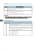
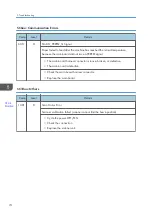
Page 72: ...ted within 6 sec after the machine was turned on temperature was less than 0 C This SC is displayed if no temperature was detected 10 times or more The fusing unit thermistor is disconnected broken or not set correctly The fusing lamp is disconnected broken or not set correctly The fusing unit is defective Check the fusing unit thermistor Check the fusing lamp Replace the fusing unit After solving...

Page 73: ...to issue this SC code and cannot be operated page 64 Executing Fusing SC Reset Code Level Details 543 A High Temperature Error Software The temperature inside the fusing unit exceeded 235 C for more than 0 5 sec This SC is displayed if the error is detected 10 times or more However the machine does not check for this error during low power mode sleep mode cover open or when the fusing lamp relay i...

Page 74: ...ted page 64 Executing Fusing SC Reset Code Level Details 545 A Fuser Full Heater Error The heating element of the fusing lamp remained at full power for more than 7 sec 100 V or 9 sec 200 V after the reload temperature was detected The machine checks for this error during standby energy save after reload or when the fusing unit is not rotating The thermistor is deformed or loose The fusing lamp is...

Page 75: ... a jam alert After this error has occurred three times the machine will shut down automatically It cannot be re started until the machine has been serviced by a service technician Check the paper transport path for any physical obstruction such as paper scraps Make sure the fusing unit has been installed correctly After solving the problem the service technician must execute FusingSCReset Otherwis...

Page 76: ...RREQ signal The main board harness connector is loose broken or defective The main board is defective Check the main board harness connector Replace the main board SC10xx Others Code Level Details 1001 D Scan Motor Error Scanner calibration failed scanner cannot find the home position Cycle the power OFF ON Check the connection Replace the scanner unit 5 Troubleshooting 74 RTB 4 Modified ...

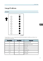
Page 77: ... different circumferences of rollers in the machine and inside the AIO Diameter mm Interval mm Component 9 5 30 Charge Roller AIO 12 27 Development roller AIO 14 6 44 Relay roller 14 2 44 6 Exit Roller 12 14 38 Transfer roller 25 06 78 7 Fusing roller 24 75 Drum AIO Image Problems 75 ...

Page 78: ... very low The low humidity causes variation in light sensitivity across the surface of the drum To prevent this problem perform the following procedure 1 Start CE Tools 2 Click Adjust Other Settings 3 Select 1 On for Low Humidity Mode When this humidity mode setting is on the drum is rotated slightly every 15 min to keep the light sensitivity consistent across the entire surface of the drum 5 Trou...

Page 79: ...6 Energy Saving Energy Save Energy Saving Modes 77 ...

Page 80: ...MEMO 78 ...

Page 81: ...MEMO 79 ...

Page 82: ...MEMO 80 EN ...

Reviews: