1.6. POWER DISTRIBUTION
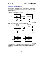
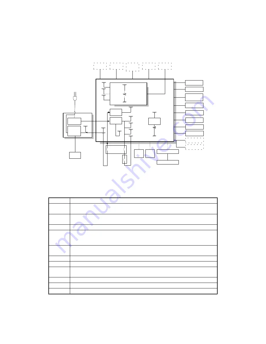
1.6.1. Distribution Diagram
The PSU su24V dc power to the FDU. The FDU converts the +24V
dc power supply to the following supplies.
+5V
This is normally on when the main switch is on.
+5VE
This is used for watching the activation signal when the machine is in energy
saving mode.
+5VLD
This supplies the laser diode. It is interrupted if the fusing unit cover interlock
switch opens.
+5VV
This is a more stable power supply than +5V. It is used for the image sensor.
+5VD
This supplies the DRAM and the page memory card on the FCE to back up the
stored data for one hour, if the power is switched off and some data is stored in
them. A rechargeable lithium battery is used to ge5VD.
+5VBAT
This supplies the system RAM on the FCE to back up the programmed data, if
the power is switched off. A lithium battery is used to ge5VBAT.
+24V
This is normally on when the main switch is on.
+24VD
This is interrupted if the fusing unit cover interlock switch opens.
+24VIN
This su24V to the fusing unit on/off switching circuit. It is interrupted if
the fusing unit cover interlock switch opens.
+24VM
This is interrupted if the machine enters energy saving mode.
-5V
This is used for the image sensor.
+12VP
This is used for the page memory card.
+24VM
+5V
+5VV
-5V
+24V
+5VE
+5VLD
+5V
+5VE
Motors
Feed Clutch
Stamp
Cooling Fan
Ozone Fan
Power Pack
Thermistor
Printer Sensors
+24VM
+24VD
Optional
Counter
Optional 100
Sheet
Cassette
Optional
Printer I/F
Main Switch
+24VD
+24VD
+5V
+5V
+24VM
+5V
FDU
PSU
Fusing
Lamp
AC
Main
Power
AC Switching
Circuit
Interlock
Switch
LDDR
Image Sensor
Book Scanner
Operation Panel
NCU
+24VD
+24VM
+5V
+24V
+5V
+5VLD
+12VD
+5V
-5V
+5vv
+5VE
+5V
DC-DC
Converter
12VP
DC-DC
Converter
24VM
24VD
24VIN
Fusing Lamp
ON/OFF
Switching
Circuit
AC115V or 230V
+5VBAT
Optional
RS232C I/F
+5V
IC
Card
+12VP
+5V
+5VD
Xenon Lamp
+24VM
Optional ADF
+24VM
+5V
+5VD
+5V
DC-DC
Converter
+24VD
FCE
+24V
H521V510.wmf
May 22nd, 1995
OVERALL MACHINE INFORMATION
POWER DISTRIBUTION
1-19