background image

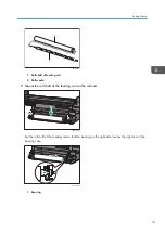
M563IC0224

29.

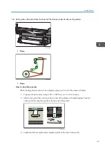
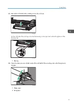
Turn the media on the feeding unit until it is evenly stretched.

30.

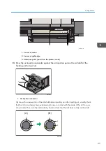
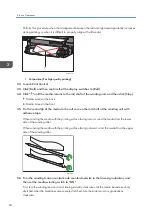
While holding the pulled media by hand so that the media does not slacken, turn on the
media feeding switch and hold the feeding roll shaft.

1

M563IC0254

1. Media feeding switch

Printing surface is outside: Turn the media feeding switch counterclockwise to set it to on.
Printing surface is inside: Turn the media feeding switch clockwise to set it to on.

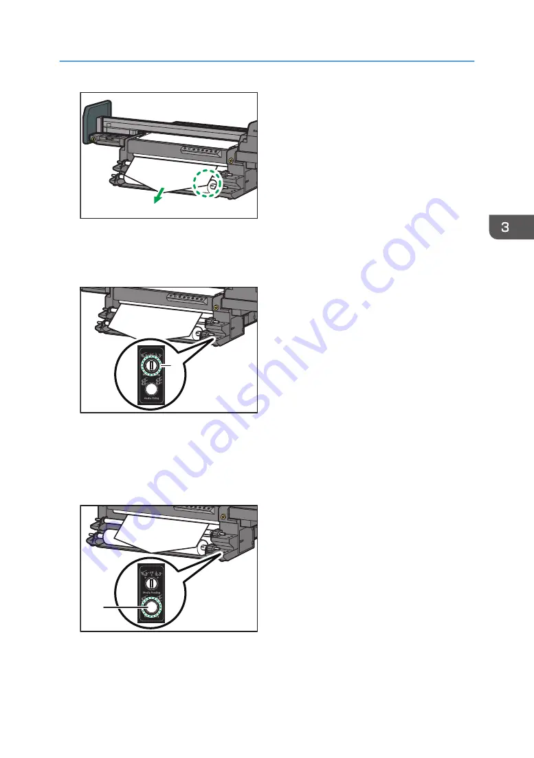
31.

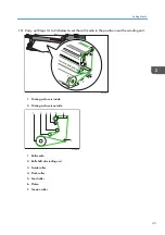
Press the media fixing button to clamp the media.

1

M563IC0255

1. Media fixing button

For high quality printing, cut the media at the position of the winding roller shaft, and proceed to
step 35.

Setting Media

53

Summary of Contents for Pro TF6251

Page 1: ...ng the machine For information not in this manual refer to the PDF files on the supplied CD Appendix Daily Care and Maintenance Maintenance and Specifications Troubleshooting Basic Operations Using Print Control Getting Started Operating Instructions Original Instructions ...

Page 2: ......

Page 3: ... Ink 15 Supported Ink 15 Storage Conditions for Ink Bottles 15 Expiration Dates of Ink Bottles 16 Precautions for Handling Ink Bottles 16 About Media 18 Size and Weight Specifications of Supported Roll Media 18 How to Store Media 18 Precautions for Handling Media 19 Notes on Flatbed Printing 20 2 Using Print Control About Print Control 21 Installing Print Control 21 How to Use the Print Control Sc...

Page 4: ... 65 When Media Skews While Feeding 66 When Roll Media Hangs Down and Makes Contact with the Floor 67 When a Media Misfeed Occurs 67 When You Have Problems Operating the Machine 69 When the Media Cannot Be Set 69 Other Printing Problems 69 Clearing Misfeeds 71 Removing Jammed Media 71 5 Maintenance and Specifications List of Consumables 75 Ink Bottles 75 Other Consumables 75 Specifications 77 Machi...

Page 5: ...Cleaning the Feed Roller 82 Cleaning the Pinch Roller 83 7 Appendix List of Print Modes 85 3 ...

Page 6: ...4 ...

Page 7: ... mainly North America Differences in the functions of Region A and Region B models are indicated by the two symbols Read the information indicated by the symbol that corresponds to the region of the model you are using Disclaimer To the maximum extent permitted by applicable laws in no event will the manufacturer be liable for any damages whatsoever arising out of failures of this machine losses o...

Page 8: ...For good output quality the manufacturer recommends that you use genuine ink from the manufacturer The manufacturer shall not be responsible for any damage or expense that might result from the use of parts other than genuine parts from the manufacturer with your products The screen shots used in this manual are displayed in English 1 Getting Started 6 ...

Page 9: ... 80 RH Altitude 2 000 m approx 6 561 7 ft or less Place the machine on a level surface The machine must be level within 5 mm approx 0 2 inches both front to rear and left to right Place the machine in a stable place where the floor is strong enough to withstand a load of 1 800 N m2 or more Avoid the following environments when locating the machine If the machine is placed somewhere where the condi...

Page 10: ...es or more 2 Right and left 100 cm 39 4 inches or more 3 Front 105 cm 41 3 inches or more 4 Depth 542 cm 213 4 inches or more 5 Width 681 cm 268 1 inches or more About Moving the Machine and the Roll Option Relocation of the machine and the roll option should be performed by your service representative Contact your service representative if you need to relocate the machine and the roll option How ...

Page 11: ...to keep the machine flat Using the machine on an unstable surface might cause an injury or unexpected accident How to use the leveling feet Rotate each adjuster clockwise to lower the leveling feet ECD116 About Operating Environments 9 ...

Page 12: ...with the machine are shown below Contact your service representative if any accessories are missing or damaged List of Included Items Roll core Tool for table adjustment Adjustment sheet Printer initial settings data CD Set of manuals 1 Getting Started 10 ...

Page 13: ...on describes the names and functions of the machine s components Do not obstruct the machine s vents Doing so can result in fire as the internal components are overheated Front View M563IC0045 1 6 5 7 8 2 3 4 Guide to Names and Functions of Components 11 ...

Page 14: ...eeding unit and winding unit 6 Fixing lever Locks and releases the clamp cover of both feeding unit and winding unit 7 Gear cover Protects the gears of the roll shafts 8 Roll core clamp Uses air pressure to secure the roll media 9 Platen This is the media feeding surface printing range Clean this area if the printed media becomes dirty See page 80 Cleaning the Platen 10 Feed roller Feeds media 11 ...

Page 15: ...to vacuum the media on the table Adjust the vacuum pressure to strengthen the vacuuming of the media if the media becomes out of position or when using warped media This is effective when the vacuum ON OFF button is on 3 Vacuum ON OFF button Turns on and off media suction If switched on suction is applied to the media through the holes in the platen 4 UV1 lamp ON OFF button Turns on and off the UV...

Page 16: ...to the right position tension is applied to the inner winding 2 Winding tension control knob Adjusts the tension of the winding roll shaft 3 Media feeding switch When the switch is set to the left position tension is applied to the outer winding When the switch is set to the right position tension is applied to the inner winding 4 Media fixing button Secures the media by clamping it between the fe...

Page 17: ...tle We recommend contacting your service representative and purchase a new ink bottle For details about how to replenish ink see Replenishing Ink Operating Instructions When using white or magenta ink it is recommended to perform head cleaning every day If the white ink is installed but it is not used perform head cleaning once a day For details see Cleaning Print Head Nozzles Operating Instructio...

Page 18: ...itions are as follows For details about storage conditions for ink bottles see page 15 Storage Conditions for Ink Bottles Ink type Color Expiration date RICOH Pro UV Ink Bottle GP120 Black Cyan Magenta Yellow White 18 months after production Use the ink bottles within 3 months after unsealing it In addition do not use an ink bottle if its shelf life has expired Precautions for Handling Ink Bottles...

Page 19: ... Shake the ink bottles well before use Do not disassemble ink bottles refill or add ink to the ink bottles Do not hit or swing around the ink bottles Doing so might cause the ink to leak About Ink 17 ...

Page 20: ...2 190 mm 86 2 inches Height 300 000 mm 11 811 0 inches Media thickness 100 432 µm Outer diameter of media Diameter of 250 mm 9 8 inches or less Roll core size inner diameter 3 inches Media weight 55 kg 121 3 lb or less 1 UV ink compatible product non penetrable media How to Store Media Take the following precautions when storing media Make sure to store media in a place that is not exposed to dire...

Page 21: ... with missing nozzles or bending lines When printing media that reflects light perform maintenance on the print heads and the UV lamp with greater frequency Reflected UV light may harden the ink on the print heads or the mist on the UV lamp resulting in malfunction If you are unsure about which side to print on check with the manufacturer of the media to determine the correct print side If one sid...

Page 22: ...s and ink stains on the roll media or affecting print quality If you intend to leave roll media in the roll option when printing on the flatbed be sure to secure both ends of the roll media to the platen with masking tape Alternatively remove the roll media from the roll option before printing 1 Getting Started 20 ...

Page 23: ...ting or stopping currently printing jobs Configuring settings related to print contents Configuring machine settings Backing up or restoring the settings Operating environment Operating system Windows 10 64 bit CPU Intel CoreTM i5 2 GHz or more Memory 16 GB or more Display resolution 1366 768 or more and 16 bit color or higher For details about the Print Control screen see page 23 How to Use the P...

Page 24: ... Pro UV Ink Bottle GP120 5 Click Install 6 Connect the machine and computer via a USB cable and then click OK 7 Click Finish A shortcut is created on the desktop If Print Control is reinstalled any contents that have been adjusted or set will be restored to their initial state After changing the main unit s ink configuration or ink it is necessary to change the component setting The display langua...

Page 25: ...ware will close Double clicking the shortcut icon on the desktop will start Print Control Startup Screen An icon is assigned to each function and these icons are displayed on the Startup screen The toolbar and other functions are described below M0DTOC5050 4 1 3 2 1 Function tab Click the icon to switch to the selected screen 2 Exit Terminates the application 3 Work area Used to configure settings...

Page 26: ...nce tab Click to display the Maintenance screen See page 28 Maintenance Screen 3 Option tab Click to display the Option screen See page 30 Option Screen Toolbar Functions of each button on the toolbar are described below M0DTOC5051 4 3 2 1 2 1 Home Click to move the carriage to the home position the right edge of the gantry 2 Click to move the carriage to the left or right 2 Using Print Control 24...

Page 27: ...n change print start position If you want to change the start position of the registered task select the task to change the print start position settings 4 Printhead Status Click to display the Medium Thickness screen and print a nozzle check pattern See Test Printing Operating Instructions 5 Mode switching Flatbed Roll Click to switch printing modes Flatbed Roll If a printing mode is switched the...

Page 28: ...g Displays the Details Setting screen 11 Stop Click to cancel printing 12 Delete Click to delete tasks 13 Add Click to select tasks 14 Print Click to start printing 15 Pause Click to pause printing Media Setting You can measure the thickness of the media and move the carriage to the height set in the setting items M563DC5051 3 1 7 2 4 5 9 8 6 1 Setting Status Specify the media thickness and width ...

Page 29: ...e settings 7 Lifter Back Zero Reset the height of the carriage to return the carriage to zero 8 Move To Print Height Raises the carriage to a height added the values specified in Medium Thickness T and Printhead to Medium Height d 9 Carriage position screen Indicates the locations of the carriage platen and media Details Setting screen Select a task in the task list and click Details Setting to di...

Page 30: ... print mode according to the color combination in use and required image quality The following are the 5 types of image quality Draft Used to check the layout You can select this only if the color set is 4C Production Prints at high speed but the quality is lowered Standard Prints at standard quality and speed Quality Prints at high quality but the printing speed is slower High Quality Prints at t...

Page 31: ...nozzle face of the print head or detach the cap as required See Capping or Detaching caps Operating Instructions 5 Clean Click to perform head cleaning See Cleaning Print Head Nozzles Operating Instructions If you are printing in roll mode automatic cleaning will be performed periodically When performing head cleaning do it before setting the media If you do perform head cleaning after the media h...

Page 32: ...ight of the carriage in Maintenance mode The height of the carriage at the end of the Maintenance mode is the same as that at the start of the Maintenance mode Weekly maintenance Option Screen Other You can configure settings for the footnote UV lamp and the carriage moving distance in the X and Y direction 2 Using Print Control 30 ...

Page 33: ... carriage in the Y direction at every click of or on the toolbar 5 X Specify the moving distance of the carriage in the X direction at every click of or on the toolbar 6 Language Selects the language to be displayed on the screen 7 Data Unit Used to select the unit displayed on the screen from Metric mm inch and mil 8 Purge Perform ink or air discharge For details about ink discharge see Dischargi...

Page 34: ...ing items see List of Setting Items on the Option Screen Other Operating Instructions When you move to another screen without clicking Apply the setting values will not be reflected in operations Make sure to click Apply after changing the setting values 2 Using Print Control 32 ...

Page 35: ...est printing See Test Printing Operating Instructions 3 Clean the print heads See Cleaning Print Head Nozzles Operating Instructions 4 Set the media See page 37 Setting Media 5 Print data See Printing Data Operating Instructions If more than 10 minutes have passed since the nozzle check perform the nozzle check again to check the discharge condition and then start printing If you change to a W typ...

Page 36: ...more before you start printing If the ink runs out during printing printing may stop If no operator will be present while printing from a roll make sure that the waste liquid tank is less than half full the liquid level in the waste liquid tank is 150 mm 5 9 inches or less before you start printing If there is not enough space in the waste liquid tank waste liquid may leak during printing Make sur...

Page 37: ...ght up M563IC0105 2 Start Print Control Turning Off the Power Standby State Before you turn off the power standby state confirm Data is not being received from a computer There is no data that has not been output yet The carriage is placed in the maintenance station 1 Exit Print Control 2 Confirm that the cooling fan for the UV lamp has stopped and then press the standby button on the front of the...

Page 38: ...get dry which may cause nozzle clogging Do not turn off the power during printing Otherwise the carriage may not return to the maintenance station If pressing any of the emergency buttons the main power switch turns off forcibly After pressing the stand by button on the control section on the front part of the machine release the emergency stop button After releasing the emergency stop button pres...

Page 39: ...Hold the roll media horizontally with both hands If you hold the roll media vertically or with one hand the roll media may fall and cause an injury The roll shaft and media together can weigh as much as 72 kg 158 7 lb When lifting lift together with one or more other person and be careful not to strain your body Lifting it carelessly or dropping it may cause an injury For details about wearing glo...

Page 40: ...a from the upper side of the feed roller If the outer surface of the media is the printing surface pull out the media from the lower side of the feed roller If the media is wound with the printing surface facing inward wind the media from the lower side of the winding roller If the media is wound with the printing surface facing outward wind the media from the upper side of the winding roller A fi...

Page 41: ...the feeding unit and raise the clamp covers The right gear cover is interlocked with the right clamp cover and opens when the clamp cover is lifted 1 2 M563IC0043 1 Fixing lever 2 Clamp cover 4 Remove the roll shaft of the feeding unit from the roll unit and then place the media on the clean and flat area Remove the roll shaft of the feeding unit with 2 or more people Setting Media 39 ...

Page 42: ...e protrusion Be careful not to injure yourself M563IC0007 1 1 Protrusion on the roll shaft of the feeding unit 6 Insert the roll shaft of the feeding unit into the roll media The direction that the media is installed on the roll shaft of the feeding unit differs depending on whether the printing surface is on the inside or outside of the roll media The roll shaft gear of the feeding unit should be...

Page 43: ...t 2 Roll media 7 Mount the roll shaft of the feeding unit on the roll unit M563IC0139 Set the roll shaft of the feeding unit so that the bearing on the right side touches the right end of the bearing case M563IC0309 㻝 1 Bearing Setting Media 41 ...

Page 44: ... maintenance is executed periodically to keep the print heads working correctly Depending on the loading position of the media printing may slow down slightly Loading the media at the edge of the platen may cause creasing If this happens load the media at the center The media detection sensors are located in two positions namely the center and right edge of the platen as shown below Load the media...

Page 45: ... of the feeding unit to inject air M563IC0128 1 1 Air injection connector A shows the cross section of the roll shaft before injecting air After injecting air visually check that the roll core clamps have extended and come in contact with the inside of the roll core as shown in B Then turn the roll media by hand to check that the roll does not slip on the shaft M563IC0040 1 2 3 1 2 3 B A Setting M...

Page 46: ...aft has been set to the winding unit remove the roll shaft from the the winding unit by following the same procedure as for removing the roll shaft from the feeding unit M563IC0044 1 2 1 Fixing lever 2 Clamp cover 12 Insert the roll core into the roll shaft of winding unit Until installing the roll shaft of the winding unit in Step 25 keep it on a flat surface where it does not get soiled M563IC00...

Page 47: ... position near the winding unit M563IC0004 1 1 2 2 1 Printing surface is inside 2 Printing surface is outside 7 3 1 4 5 6 2 M563IC0019 1 Roll media 2 Roll shaft of winding unit 3 Guide roller 4 Pinch roller 5 Feed roller 6 Platen 7 Tension roller Setting Media 45 ...

Page 48: ...㼑 㻯㼡㼠 㻟㻜㻌㼠㼛㻌㻡㻜㼏㼙 㻔㻝㻝㻚㻤㻌㼠㼛㻌㻝㻥㻚㻣㻌 㼕㼚㼏㼔㼑㼟㻕 M563IC0050 15 Pass the leading edge of the roll media under the tension roller After feeding the media into the tension roller keep feeding it until its leading edge emerges on top of the platen 1 M563IC0221 1 Tension roller 1 M563IC0112 1 Tension roller 3 Basic Operations 46 ...

Page 49: ...ch as polyester paper pull it out to the platen as follows 1 Prepare a sheet cut into a strip 100 1000 mm 3 9 39 4 inches 2 Attach one end of the cut sheet to the center of the platen with masking tape Pass the other end of the strip through from the far end of the platen M563IC0135 3 Staple the left and right ends 2 stapled points of the strip to the media Setting Media 47 ...

Page 50: ...les are left on the media the media path or feed roller may become scratched 17 Open the front cover of the roll option 㻝 M563IC0323 1 Front cover 18 Insert the tip of the roll media between the feed roller and the exterior and then pass it between the feed roller and pinch roller Before passing the media curl the tip of it inwards 3 Basic Operations 48 ...

Page 51: ...rd you 1 M563IC0125 1 Guide roller 20 Close the front cover 21 Loosen the left and right tension bar fixing levers Be sure to perform the work with two people and be careful not to get your hands caught Take care when loosening the fixing lever because it may move the tension bar M563IC0326 1 1 1 Fixing lever Setting Media 49 ...

Page 52: ...e tension bar to a smaller angle Media with low tension thin media or media that stretches easily such as polyester Set the angle of the tension bar to a larger angle M563IC0327 1 1 2 2 1 Angle guide 2 Arrow 23 Lock the left and right fixing levers Make sure that the left and right tension bars are at the same angle 24 Make sure that the left and right fixing levers are set in the same position Ma...

Page 53: ...t of the winding unit so that the bearing on the right side touches the right end of the bearing case M563IC0314 㻝 1 Bearing 26 Close the clamp covers at both ends of the roll shaft of the winding unit so the fixing levers engage M563IC0042 2 1 1 Clamp cover 2 Fixing lever Setting Media 51 ...

Page 54: ...the roll core by hand to check that the roll core does not slip on the shaft M563IC0040 1 2 3 1 2 3 B A 1 Roll core clamp 2 Roll core 3 Roll shaft 28 Align the right edge of the roll media that is mounted on the roll shaft of the feeding unit and the right edge of the roll media that was passed out If it is difficult to align the right edge of the roll media feed more of the media before trying to...

Page 55: ... 1 M563IC0254 1 Media feeding switch Printing surface is outside Turn the media feeding switch counterclockwise to set it to on Printing surface is inside Turn the media feeding switch clockwise to set it to on 31 Press the media fixing button to clamp the media 1 M563IC0255 1 Media fixing button For high quality printing cut the media at the position of the winding roller shaft and proceed to ste...

Page 56: ... of the media to the roll core on the roll shaft of the winding unit with adhesive tape When winding the media with the printing surface facing inward wind the media from the lower side of the winding roller When winding the media with the printing surface facing outward wind the media from the upper side of the winding roller M563IC0027 36 Turn the winding tension control knob counterclockwise to...

Page 57: ... to the lowest graduation the media fixed to the roll core may become detached M563IC0256 1 1 Media winding switch 37 Click on Print Control to roll the media around the roll core a few time approximately 500 mm 19 7 inches 38 Click Stop 39 Turn on Vacuum button 40 Set the vacuum pressure control knob to 0 41 Use the vacuum pressure control knob to increase the suction until there is no floating o...

Page 58: ... W have been specified manually click Apply and then click Close 47 Enter the value of the print start position in the X of Print Position on the Operation screen Check the print start position by referring to the scale on the platen The positions of the scale of the roll shaft and the scale of the platen are different Be sure to use the scale on the platen as a guide when entering the value 48 Ad...

Page 59: ... If you cannot eliminate floating or waviness from the media see page 65 When Media Is Not Fed Properly Setting Media 57 ...

Page 60: ... part moved back such as leaving roller marks on it If this happens press to feed the media Perform no other operations while the test pattern is printing An error will occur and test pattern will not print if There is a misfeed The machine is performing maintenance operations The machine has run out of ink The machine has run out of media Before adjusting ensure that there is no media floating or...

Page 61: ... 4 As required specify Medium Thickness and then click Print The inspection pattern is printed 5 Click Step Correction Adjust and then select the print mode 6 As required specify Medium Thickness and then click Print The adjustment pattern is printed 7 Select the value 4 to 4 of the clearest image on the adjustment pattern In this example 1 is selected 4 3 2 1 0 1 3 4 STEP 1 4_4C_High Quality TIME...

Page 62: ... to 6 again to print the inspection and adjustment patterns 11 Compare the inspection patterns before and after adjustment to check whether the deviation has been corrected If further adjustment is required repeat Steps 7 to 11 Example of image before adjustment M563IC0132 Example of image after adjustment deviation corrected 3 Basic Operations 60 ...

Page 63: ... lines are visible and image quality defects such as blurred text and vertical lines occur reload the media and make sure it is loaded correctly For information on how to correct skews see page 66 When Media Skews While Feeding 12 After the adjustment click Medium Config 13 Enter the name of the configured setting and then click Add The adjusted setting is saved 14 Click Close Adjusting the Media ...

Page 64: ...t Control operation screen click Media Setting 2 Click Step Correction 3 Click Medium Config 4 Select the name of the setting to be applied and then click Load You can click Rename to rename the setting 5 Click Close 3 Basic Operations 62 ...

Page 65: ... the Platen 2 Clean the tension roller For details about how to clean the tension roller see page 82 Cleaning the Tension Roller 3 Clean the feed roller For details about how to clean the feed roller see page 82 Cleaning the Feed Roller The back of the transparent media becomes scratched The media path is soiled with dirt or ink particles Perform the following 1 Clean the platen and the feed rolle...

Page 66: ...media see page 65 When Media Curls While Feeding After loading the media correctly perform head cleaning Ink adheres to the media The print head nozzle faces are dirty The cap is dirty Perform the following 1 Clean the capping station and the area around print head nozzles See Cleaning the Capping Station or Cleaning Around the Print Heads Requests for Daily Care and Maintenance 2 Cleaning the noz...

Page 67: ...evel see Setting Media on a Table Operating Instructions Media curls before printing Set media to the winding unit Media floating decreases Recommended media is not being used Use recommended media For details about recommended media see page 18 Size and Weight Specifications of Supported Roll Media The machine moves or the winding unit is not aligned When the machine moves and work to make it lev...

Page 68: ...d If media floating cannot be resolved contact your service representative When Media Skews While Feeding Cause Solution Media has not been set straight into the media input location Reset the media correctly For details about setting media see page 37 Setting Media If using media without resetting it first feed about 1 m approx 39 37 inches of the media from the Origin Setting screen The machine ...

Page 69: ...ing the roll media to slip Replace the roll media spool When a Media Misfeed Occurs Problem Cause Solution Media rises on the platen Media has not been set in the winding unit The following problems exist with the leading edge of roll media The leading edge is damaged Adhesive tape is sticking to it The corners are folded The leading edge is cured Recommended media is not used The platen is staine...

Page 70: ...e media is dirty The media is floating For details about solving media jams see page 71 Clearing Misfeeds When the media is dirty see page 63 When the Printed Media Becomes Dirty When the media is skewed see page 65 When Media Curls While Feeding 4 Troubleshooting 68 ...

Page 71: ...edia on a Table Operating Instructions Clean the platen For details about how to do this see page 80 Cleaning the Platen Turn on the pinch roller For details about how to turn on the pinch roller see page 37 Setting Roll Media Other Printing Problems Problem Solution An error occurs when printing a test pattern of the media feed adjustment Check whether the media is set correctly and whether the m...

Page 72: ...clogging clean the print heads For details about head cleaning see Cleaning Print Head Nozzles Operating Instructions Adjust the feeding quantity to the proper feed quantity For details about adjustment see page 58 Adjusting the Media Feed Quantity Adjust the drop position For details about adjustment see Administrator Mode Guide 4 Troubleshooting 70 ...

Page 73: ...e on the machine Not doing so could result in burns When removing jammed media make sure not to trap or injure your fingers Be sure to wear three sets of protective gloves in the following order nitrile gloves polyethylene gloves and nitrile gloves When removing jammed media do not turn off the power To prevent media misfeeds do not leave any torn scraps of media inside the machine Doing so may ca...

Page 74: ...f the carriage clockwise to raise the carriage 4 Cut media from the roll shaft of the winding unit 1 M563IC0318 1 Cutting position 5 Cut the jammed media Do not cut it on the feed roller Doing so may scratch the roller 1 M563IC0119 1 Cutting position 6 Remove the separated media 4 Troubleshooting 72 ...

Page 75: ...s to move the carriage above the media 12 Click Detect Medium Height The medium thickness is detected 13 Install the cover on the top of the carriage cover If ink adheres on the internal components of the machine while removing jammed media the back side of media may get dirty If the back side of media gets dirty after the jammed media is removed clean the platen For details about cleaning see pag...

Page 76: ...4 Troubleshooting 74 ...

Page 77: ... Pro UV Ink Bottle Magenta GP120 342539 2 RICOH Pro UV Ink Bottle Yellow GP120 342540 2 RICOH Pro UV Ink Bottle White GP120 342541 2 Before there is no remaining ink in the ink tank we recommend purchasing it soon Ink consumable is not covered by warranty However if there is a problem contact the store where you purchased it For details about storage conditions for the ink bottles see page 15 Stor...

Page 78: ...y Waste cloth paper towel 1 box 50 sheets Non woven fabric 1 box 100 sheets Polyethylene gloves 7 pairs Nitrile gloves 14 pairs Cleaning stick 12 sticks Cleaning Liquid Name Sales unit Cleaning liquid 6 bottles 5 Maintenance and Specifications 76 ...

Page 79: ...ality Maximum resolution 635 1 800 dpi Maximum print size 2 190 300 000 mm approx 86 2 11 811 0 inches Supported media For details see page 18 Size and Weight Specifications of Supported Roll Media Waste ink tank Bottle system 2 5 L Operating environment Temperature 15 30 C 59 86 F Humidity 40 80 Power supply used mainly Europe and Asia AC400 V 3P N PE 25 A or more 50 60 Hz mainly North America AC...

Page 80: ...red in a cold place for a long period of time If ink freezes it may become unusable as it may deteriorate Make sure to store ink in an environment where ink will not freeze Supported ink colors Black cyan magenta yellow and white ink Ink tank capacity 2 5 L Ink supply method Ink bottle 1 0 L For details about storage conditions for the ink bottles see page 15 Storage Conditions for Ink Bottles For...

Page 81: ...g If ink flushing liquid and displacement liquid come into contact with your clothing wash the stained area with water When removing jammed media replacing media or performing maintenance on the machine avoid getting ink flushing liquid and displacement liquid on your skin If ink flushing liquid and displacement liquid come into contact with your skin wash the affected area thoroughly with soap an...

Page 82: ...aten The platen is susceptible to becoming dirty with bits of media Also if ink is affixed to the platen it may not be possible to successfully feed media when printing If the platen is dirty clean it If a fragment of the cured ink is left on the platen it may deform the media or cause a vacuuming defect Completely remove such fragments by using a vacuum cleaner etc If there are any particles on t...

Page 83: ...on the edges of the platen where the roll media emerges M563IC0046 3 If ink has cured in the vacuum holes scrape it off with a pointed object and remove it You can also use an adhesive tape such as a duct tape to remove the ink ECD328 1 1 Vacuum holes After cleaning check that the platen is dry before setting media Maintenance When Needed 81 ...

Page 84: ...th neutral detergent to wipe off the ink M563IC0321 1 1 Tension roller After cleaning check that the tension roller is dry before setting media Cleaning the Feed Roller If bits of media or ink are affixed to the feed roller it may not be possible to successfully feed media when printing Clean the feed roller regularly 1 Remove dust and dirt such as bits of media on the surface of the feed roller w...

Page 85: ... before setting media Cleaning the Pinch Roller If bits of media or ink are affixed to the pinch roller it may not be possible to successfully feed media when printing Clean the pinch roller regularly 1 Open the front cover 㻝 M563IC0323 1 Front cover Maintenance When Needed 83 ...

Page 86: ...22 1 Pinch roller 3 Wipe off dirt on the pinch roller by using a paper towel If ink is cured too hard to wipe off use non woven fabric that has been applied with neutral detergent to wipe off the ink 4 Close the front cover After cleaning check that the pinch roller is dry before setting media 6 Daily Care and Maintenance 84 ...

Page 87: ... 300 dpi 1 2_4C_Standard 635 dpi 600 dpi 1 3_4C_Quality 635 dpi 900 dpi 1 4_4C_High Quality 635 dpi 1 800 dpi 2 1_W 4C_Production 635 dpi 300 dpi 2 2_W 4C_Standard 635 dpi 600 dpi 2 3_W 4C_Quality 635 dpi 900 dpi 2 4_W 4C_High Quality 635 dpi 1 800 dpi 3 1_4C W_Production 635 dpi 300 dpi 3 2_4C W_Standard 635 dpi 600 dpi 3 3_4C W_Quality 635 dpi 900 dpi 3 4_4C W_High Quality 635 dpi 1 800 dpi 85 ...

Page 88: ...MEMO 86 ...

Page 89: ...MEMO 87 ...

Page 90: ...MEMO 88 EN GB EN US EN AU M563 7003A ...

Page 91: ... 2020 2021 Ricoh Co Ltd ...

Page 92: ...M563 7003A AU EN US EN GB EN ...

Reviews: