Boards
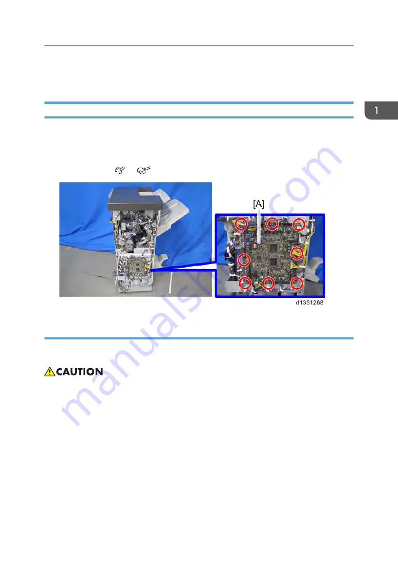
Main Board
1.
Remove the following covers.
• Rear upper cover (page 7)
• Rear lower cover (page 7)
2.
Main board [A] ( ×8,
×all)
When replacing the main board
This board has two blocks of dip switches. When you reinstall the main board, follow the procedure
below regarding the dip switch settings.
• Keep the EEPROM away from any objects that can cause static electricity. Static electricity can
damage EEPROM data.
• Make sure that the DIP-switch settings on the old main board are the same for the new main board.
Do not change the DIP switches on the main board in the field.
1. Check the settings of dip switch [A] on the old main board.
2. Replace the main board.
3. Change the settings of dip switch [A] on the new main board to match the settings on the old main
board.
4. Make sure the switches of dip switch [B] on the new main board are all OFF.
Boards
19
Summary of Contents for SR3160
Page 2: ......
Page 18: ...8 End fence A 2 Left Cover D689 Only 1 Upper tray A 1 1 Replacement and Adjustment 16...
Page 19: ...2 Rear mold bracket A 1 3 Front mold bracket A 1 4 Shift tray bracket A 4 Exterior Covers 17...
Page 20: ...5 Left cover A 3 1 Replacement and Adjustment 18...
Page 25: ...7 Pulley A hook 1 8 Screws from the rear side of the finisher 6 Corner Stapling Unit 23...
Page 67: ...7 Disconnect the connectors shown below 2 Booklet Unit D688 Only 65...
Page 75: ...6 Disconnect the connectors shown below 11 Booklet Unit D688 Only 73...
Page 76: ...7 Disconnect the connectors shown below 2 1 Replacement and Adjustment 74...
Page 81: ...3 Fold plate bracket A 2 4 Booklet paper exit guide plate A 4 Booklet Unit D688 Only 79...
Page 87: ...3 Booklet bottom fence HP sensor A 1 1 Booklet Unit D688 Only 85...
Page 89: ...Punch Unit 87...
Page 96: ...MEMO 94...
Page 97: ...MEMO 95...
Page 98: ...MEMO 96 EN...


