background image


T

echnical


B

ulletin


PAGE: 2/3 

Reissued:27-Mar-14 

Model: 

Taurus-C1a/C1b (D074/D075)


Date: 

26-Jan-14


No.: 

RD074115a 


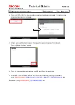
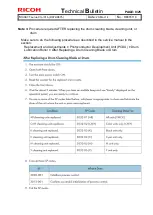
4.  Touch “01 SP->SD” on the operation panel and wait approximately 1 minute for the 

download process to complete. 


5.  When successfully downloaded, the operation panel displays “Completed”. 

Touch “[Start] Confirm”

 to exit. 


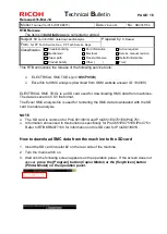
5.  Turn off the machine and remove the SD card from the card slot. 
  

6.  In the SD card, the SMC data is saved with the following naming convention: 

splist_

[Serial Numbers]

_

[Date/Time when the SMC is taken(YYYYMMDDHHmmss)]

.csv


Example

: splist_

V9000500010

_

20130926063542

.csv

Summary of Contents for Taurus-C1a Series

Page 1: ...August 2014 production Not available 1 11 D0746885C December 2012 production Not available 1 05 D0746885B June 2011 production Not available 1 04 D0746885A 1st Mass production Not available EU Models Version Program No Effective Date Availability of RFU 1 12 D0746886D August 2014 production Not available 1 11 D0746886C December 2012 production Not available 1 05 D0746886B June 2011 production Not ...

Page 2: ...b Support 1 09 or newer Specification Changes 1 The following adjustment functions are added to Custom Paper Settings for Administrators See Notes for Users of TCRU ORU manuals for details 44 Txt Ppr Ppr Trns Voltage B W Side 1 45 Txt Ppr Ppr Trns Voltage B W Side 2 46 Txt Ppr Paper Trnsf Voltage FC Side 1 47 Txt Ppr Paper Trnsf Voltage FC Side 2 48 Txt Ppr Ppr Trns Isolatn Voltag Side 1 49 Txt Pp...

Page 3: ... to use the AC transfer function with the machine produced before December 2012 the AC power supply unit must be installed See RTB RD074097 Firmware Version Engine 1 63 04 or newer System Copy 1 11 or newer OpePanel EXP 1 11 or newer Language Install 1 07 or newer Web Support 1 09 or newer Specification Changes 1 The following adjustment functions are added to Custom Paper Settings for Administrat...

Page 4: ...e SP1151 013 Pressure Setting Pressure Position 3 is available in the Advanced Setting for Skilled Operators 0705 This sets the length of time pressure is increased on the fusing roller by the pressure roller for printing Envelopes 1 11 Firmware requirements If you apply this firmware to activate the AC transfer function be sure to upgrade all the firmwares listed in the following table together a...

Page 5: ...o RD074001d Version Modified Points or Symptom Corrected 45 Txt Ppr Ppr Trns Voltage B W Side 2 46 Txt Ppr Paper Trnsf Voltage FC Side 1 47 Txt Ppr Paper Trnsf Voltage FC Side 2 48 Txt Ppr Ppr Trns Isolatn Voltag Side 1 49 Txt Ppr Ppr Trns Isolatn Voltag Side 2 1 06 1st Mass production ...

Page 6: ...e updated via RFU or SD card Not available The firmware can only be updated via SD card Version Modified Points or Symptom Corrected 1 08 Specification Change SP1151 013 Pressure Setting Pressure Position 3 is available in the Advanced Setting for Skilled Operators 0705 This sets the length of time pressure is increased on the fusing roller by the pressure roller for printing Envelopes 1 07 Firmwa...

Page 7: ...oved accordingly with the instructions for jam display code D The following peripherals are supported starting from this version Buffer Pass Unit Type 5010 Trimmer Unit TR5040 Cover Interposer Tray CI5020 High Capacity Stacker SK5020 Ring Binder RB5010 Please make sure that ALL versions listed below are updated concurrently Mainframe Program Name Version Program No Engine 1 54 04 D0745404C TDCU 01...

Page 8: ... available 1 63 04 D0745404K December 2012 production Not available 1 62 04 D0745404J December 2012 production Not available 1 61 04 D0745404H September 2012 production Not available 1 60 04 D0745404G May 2012 production Not available 1 59 04 D0745404F February 2012 production Not available 1 58 04 D0745404E December 2011 production Not available 1 56 1 04 D0745404D September 2011 production Not a...

Page 9: ...s Modifying these SP values will set the default value back to 10 Once modified the new default of 3 value cannot be retrieved Modify these SP values only when they need to be set to a value higher than 10 which should be decided based on the job operation requested by your customer The above limitations will be resolved in the succeeding controller firmware version to be released 1 65 04 Specific...

Page 10: ... on BK5030 when using CF5030 2 Invalidity of Adjustment Settings for Operators 0405 Adjust Punch Position With Feed Direction when switching the main power off on or recovering from energy save mode 3 BK204 error on BK5030 during long running job 1 61 04 Symptom Corrected SC36x caused by bug Modification of toner refresh mode algorithm The toner yield becomes longer by new refresh mode algorithm u...

Page 11: ...ure and prevents condensation SP1945 018 This SP specifies ON 1 or OFF 0 of the anti condensation function 2 The following SP for adjusting the sub scan registration was added SP1 501 001 Please see RTB RD074022a for details 3 The default values for the following SPs were modified for better image quality SP1984 104 170 180 SP1984 125 165 180 SP1984 110 170 160 SP1984 117 170 160 1 56 1 04 Engine ...

Page 12: ... applicable for both color and mono color originals The following peripherals are supported starting from this version Buffer Pass Unit Type 5010 Trimmer Unit TR5040 Cover Interposer Tray CI5020 High Capacity Stacker SK5020 Ring Binder RB5010 Please make sure the firmwares are updated to the versions listed below for new site installations Bug fixes hereafter will also be based on this combination...

Page 13: ...rrent System version in SP7801 Proceed to Step 2 2 if the current version is either V1 02 or V1 03 Update is not required if the current version is V1 05 or newer Step2 2 Update the following 6 firmwares concurrently See section Firmware Update Procedure of the service manual Program Name Before the Update After the Update 1 System Copy D0745773B V1 02 or D0745773C V1 03 D0745773D V1 05 2 WebSys D...

Page 14: ...ymptom Corrected 017 Special Mode Coefficient2 SP3 533 001 Interrupt ProCon Set Interval Set BW 0 500 SP3 533 011 Interrupt ProCon Set Interval Set FC 0 500 Step2 5 Exit the SP mode and power cycle the machine to complete the procedure 1 05 1 04 1st Mass production Note DO NOT install this Firmware to the proto type machines ...

Page 15: ... No Availability of RFU Rev 19 00 RD0755785_R19 Not Available Rev 18 00 RD0755785_R18 Not Available Rev 17 00 RD0755785_R17 Not Available Rev 16 00 RD0755785_R16 Not Available Rev 15 00 RD0755785_R15 Not Available Rev 14 00 RD0755785_R14 Not Available Rev 13 00 RD0755785_R13 Not Available Rev 12 00 RD0755785_R12 Not Available Rev 11 00 R0755785_R11 Not Available Rev 10 00 R0755785_R10 Not Availabl...

Page 16: ...0023A RE0023B Corrected LE Paper Transfer Current FC 140 to 200 RE0024 RE0024A RE0024B Corrected Fusing Temp 175 to 180deg and LE Paper Transfer Current FC 170 to 120 RE1303 RE1303A RE1303B Corrected Fusing Temp 170 to 165deg and Overall Rank B to A RE1312 RE1312A RE1312B Corrected Fusing Temp 175 to 170deg RE1589 RE1590 RE1591 RE1592 RE1593 RE1594 RE1595 RE1596 Corrected LE Paper Transfer Current...

Page 17: ... to Recycled 8 00 Add 22 Media RE0219 Correct the Paper Weights to 183gsm from 175gsm 18 media RE1008 RE1423 RE1704 RE1705 RE1706 RE1707 RE1708 RE1709 RE1710 RE1711 RE1712 RE1713 RE1714 RE1715 RE0313 RE0314 RE0315 RE0317 Corrected Type to ST3 from CU 7 00 Add 84 Media RE1423 RE1579 Correct the Paper Type 6 00 Add 17 Media 5 00 Add 18 Media 4 00 RE0185 RE0186 Image Quality rank was changed and desc...

Page 18: ...y of an SD card and name the folder mqp 2 Copy the paper database file into the mqp folder and then rename the copied file library mqp 3 Make sure that the machine is turned off 4 Insert the SD card which has the library mqp file into SD card Slot 2 lower slot on the right side of the controller box 5 Turn on the machine 6 Make sure that the data version of the SD card is newer than the data versi...

Page 19: ... revision Retrofit information Product Safety Other Firmware Tier 2 This RTB has been issued to announce the firmware release information for the ADF_MCKINLEY_B Version Program No Effective Date Availability of RFU 01 050 05 D5225300B 1st Mass production Available Note Definition of Availability of RFU via Remote Available The firmware can be updated via RFU or SD card Not available The firmware c...

Page 20: ...id not allow creation of PDF files under the condition as described as case 3 below The modified specification allows creation of security set PDF files even under the condition where the Document Password is not set and the Master Password is set Security Settings for PDF Files Encrypting PDF files Security permissions Current Specification Modified Specification case 1 Document password NOT set ...

Page 21: ...ing the PCDU Replacement and Adjustment Common Procedures Removing PCDUs Replacement and Adjustment Photoconductor Development Unit PCDU Correction 4 Deletion of Description on Sponge Seals Replacement and Adjustments Photoconductor Development Unit PCDU Drum Cleaning Blade Drum Lubrication Blade Correction 5 Revised After Replacement Procedure for ITB Lubrication Blade Replacement and Adjustments...

Page 22: ...rews to Fix the Operation Panel Installation Main Machine D074 D075 Accessories D074 D075 Pan head M4x6 screws Q ty 4 was added to the diagram below Pan head M4x6 screws Q ty 4 was added to the list of accessories Change in quantity of the screw indexed 17 M4x8 in the table 15 pcs 11 pcs Add M4x6 screw x4 ...

Page 23: ...22 Jun 2011 No RD074015a The 4 screws holding the back of the operation panel should be the pan head screws 6mm not the hexagonal screws 8mm IMPORTANT Screws longer than 6mm could damage the PCB A B 1 INCORRECT CORRECT Pan head screws M4x6 Hexagonal screws M4x8 ...

Page 24: ...cedure The doors should remain closed Connect Main Machine to Power Source and Power On Execute this procedure Door open alert will not appear Install Developer Delete this procedure Do SP3025 001 Delete this procedure Close Both Front Doors Delete this procedure The doors are closed during the process Start Toner Fill Execute this procedure as described in the service manual Clean and Lubricate t...

Page 25: ...nstall Developer SP3024 001 K SP3024 002 C SP3024 003 M SP3024 004 Y Yes 8 Developer File OK SP3025 001 Results for YMCK reading left to right Yes 9 Apply Lubricant 1 Open right front door 2 SP2310 001 3 Close right door 10 Close Front Door Yes 11 Wait for Warmup Ready Wait 5 min for the audible beep and the Ready message on the operation panel Yes 12 Manual Toner Fill SP3051 001 Yes 13 Cleaning S...

Page 26: ...PAGE 6 14 Model Taurus C1 D074 D075 Date 22 Jun 2011 No RD074015a Summary of correction 2 Please apply the procedure indicated in red when installing a new unit and apply the procedure in blue when replacing the developer ...

Page 27: ... Notes on Setting the PCDU Replacement and Adjustment Common Procedures Removing PCDUs Replacement and Adjustment Photoconductor Development Unit PCDU The following instruction was added Please note that this instruction will apply to procedures involving replacements of any of the PCDU components ...

Page 28: ...um Cleaning Blade Replacement and Adjustments Photoconductor Development Unit PCDU Drum Lubrication Blade The following description was deleted from the above 2 sections in the service manual This description was deleted because the Sponge Seals are registered as service parts and can be replaced Please note that once removed these sponge seals cannot be reused and must be replaced with new sponge...

Page 29: ... 3 Remove the PTR unit 4 Turn the main power switch ON and close both front doors 5 Enter the SP mode 6 Reset the counter for the replaced unit or parts 7 Open the right front door and access SP2310 1 Force Lubricant Belt Cleaning 8 Immediately after the above step close the right front door to run the above SP 9 Wait for about 5 minutes When you see Completed displayed on the operation panel you ...

Page 30: ...kwise to retract the blades from the ITB 5 Remove the PTR unit 6 Turn the main power switch ON and close both front doors 7 Enter the SP mode 8 Reset the counter for the ITB belt 9 Open the right front door and execute SP2310 1 Force Lubricant Belt Cleaning 10 Immediately after the above step close the right front door to run the above SP 11 Wait for about 5 minutes When you see Completed displaye...

Page 31: ...80 C 176 F indicating that the thermistor has shorted out Cycle the machine off on IOB harness loose disconnected broken defective CK YM laser unit defective IOB defective SC576 A Hot Roller NC Sensor Sensor 7 Poor Connection The hot roller NC sensor infrared thermistor on top of the fusing unit detected temperature less than 0C for 75 sec Do SP5810 to cancel the fatal error Sensor disconnected Se...

Page 32: ...Quality Problems Color Toner Spotting Staining Colored Spots Coat the drum surface with lubricant powder p n B1329700 Troubleshooting Troubleshooting for Image Quality Problems Color Loss White Dots Lines Solution 1 To identify the affected color print three full page solid fill SP2 109 003 26 A3 or DLT sheets or each of cyan magenta black and green Because it is difficult to identify white spots ...

Page 33: ...tes on Installing the Decurler Unit Installation Decurler Unit Notes on handling the Decurler Unit have changed in accordance with the attachment of the mylars to the Decurler Unit entrance gate Bracket D must also be removed in order to install the Decurler Unit Current Description Revised Description ...

Page 34: ...Technical Bulletin PAGE 14 14 Model Taurus C1 D074 D075 Date 22 Jun 2011 No RD074015a Current Description Revised Description ...

Page 35: ... details see p 76 Removing the Transfer Unit 4 Close the right drawer with the transfer unit detached 5 Reconnect the power cord to the power source 6 Turn the machine s main power switch to ON close the left and right front covers and then wait for the machine to warm up 7 Access the Adjustment Settings for Skilled Operators menu See p 18 Accessing the Adjustment Settings for Skilled Operators 8 ...

Page 36: ...Skilled Operators NOTE Although the alert message cover open is on the operation panel press the User Tools key on the operation panel 8 Reset the replaceable parts counter for the replaced cleaning unit for intermediate transfer belt See p 20 Resetting the Replaceable Parts Counter 9 Open the right front door and on the Adjustment Settings for Skilled Operators menu press 0303 ITB Manual Lubricat...

Page 37: ...ound is generated from the mainframe Cause Friction between the drum shaft and the spring plate located behind the PCDU cover Solution Pull out the PCDU and grease the tip of the drum shaft Grease Grease SHIN ETSU KS 660 p n G0049668 Apply approximately φ1mm 2mm of grease to the tip of the shaft as shown in the left photo Although the photos above are taken with the PCDU inner cover removed the PC...

Page 38: ... to make the following request regarding the print samples included at the RCL factory as accessories to the Taurus Request Please make sure all the print samples are collected after site installations and are NOT left at customer sites If not needed you may discard the samples Background These print samples are printed and packaged at the RCL factory and they are supposed to be used as a referenc...

Page 39: ...lt 3 Print Test Pattern Overall M 26 Full Dot Pattern 3 Magenta 15 default 15 default 15 default 15 default 4 Print Test Pattern Overall Y 26 Full Dot Pattern 4 Yellow 15 default 15 default 15 default 15 default 5 Print Test Pattern Overall R MY 26 Full Dot Pattern 1 Full Color 0 0 15 default 15 default 6 Print Test Pattern Overall G CY 26 Full Dot Pattern 1 Full Color 0 15 default 0 15 default 7 ...

Page 40: ...nditions Toner developer degradation Refresh toner Steps 2 3 Replace developer Step 4 Recommended Action Step1 Are the markings on the drive gear and coupling gear of the development roller aligned Yes Go to step 2 No Do the Development roller Drive gear Coupling gear alignment procedure described in the last part of this bulletin Print the image showing the problem Has the problem been resolved Y...

Page 41: ...etting enables the system to refresh toner at job end Note Increasing the value in SP3 820 022 will reduce the toner yield If the machine produces high P J the effect brought from this SP modification may not be enough It is recommended to monitor for a while to verify the effect Step 4 Is the s n of the development unit smaller than the following Originally installed in mainframe TP0130500289 Pro...

Page 42: ... the PCDU and look for a white marking on the gear as shown in the photo below How to identify the marking on the Coupling Gear on the Development Unit Pull out the PCDU and locate the coupling gear at the rear side If marked the coupling gear could be marked in two ways either in white only or in white and pink If marked only in White White marking to be aligned with the white marking on the driv...

Page 43: ...r of the development unit counterclockwise viewed from the rear side Example For example if the white marking on the drive gear is at 8 o clock viewed from the front side turn the coupling gear on the development unit counterclockwise so that the marking on the coupling gear is at 4 o clock viewed from the rear side of the development unit The coupling gear is marked at the factory for each develo...

Page 44: ...The original specification did not allow creation of PDF files under the condition as described as case 3 below The modified specification allows creation of security set PDF files even under the condition where the Document Password is not set and the Master Password is set Security Settings for PDF Files Encrypting PDF files Security permissions Current Specification Modified Specification case ...

Page 45: ...oser Tray CI5020 High Capacity Stacker SK5020 Ring Binder RB5010 Please make sure that ALL versions listed below are updated concurrently Mainframe Program Name Version Program No Engine 1 54 04 D0745404C TDCU 01 03 54 D0745528C Web Uapl 1 02 D0745778B Web Support 1 05 D0745777B Language 1 02 D0746890A OpePanel_USA 1 05 D0746885B Opepanel_EUR 1 05 D0746886B System 1 05 D0745773D Fiery Server Syste...

Page 46: ...cation Troubleshooting Mechanical Paper path Part information Electrical Transmit receive Action required Service manual revision Retrofit information Product Safety Other Tier 2 Symptom Frequent SC496 MUSIC Sensor Error Printed line images are not reproduced as straight lines but appear curved although hardly visible to the naked eye Cause Lens assembly unit is slightly off position possibly beca...

Page 47: ...on 2181 020 Difference Sub Left Y x 2181 021 Difference Sub Center Y y 2181 022 Difference Sub Right Y z 3 Calculate the misalignment level by applying the above results to the following formula x z 2 y 4 If the absolute value obtained from the above calculation is higher than 75 the Lens Assembly unit is out of position Follow the procedures described in Setting the Lens Assembly Unit If the abso...

Page 48: ... Lens Assembly unit is set properly 7 Print out the Shading test pattern from SP4417 001 18 Check the image quality of the pattern to check that there are no image defects possibly caused by foreign materials in the laser unit Modification Plan The laser unit will be modified to prevent the lens assembly unit from becoming loose The modification is scheduled to complete in late November 2011 An ad...

Page 49: ...letions of descriptions Please refer to the following pages for details Safety Symbols Trademarks Conventions The following description was added These manuals cover three machines M074 M075 and M044 The M074 and M075 are the copier versions They both have the ARDF and scanner unit The M044 is the printer version It has neither ARDF nor scanner unit The following notations are used in text to indi...

Page 50: ...s and Names Taurus P1 was added to the production list Main Machines Base Machine Description of M044 was added The Production No numbers in the 2nd column of the table below are used exclusively in the manuals to refer to different machines The names in the 1st and 3rd columns are not used in the service manuals Production Name Production No Model Name Taurus C1a 65 ppm D074 Pro C651EX Taurus C1b...

Page 51: ...erforms corner stapling only The finisher 7 in the illustration above is the Booklet Finisher D512 M044 No Unit Comment 1 Main machine M044 Printer 2 Decurler Unit D544 Inside the left side of the main machine 3 A3 DLT LCIT D516 Only one LCIT available 4 Multi Bypass Tray D517 Requires LCIT 5 Buffer Pass Unit D548 Not shown This is a cooling unit recommended for use with the Multi Folding Unit 6 C...

Page 52: ...on 2 Paper entrance from LCIT and paper registration and 3 Inverter duplex path The number of shift rollers has been increased from two to four to accommodate postcards and large size thick paper To support printing on 300 g m2 paper and duplex printing on paper up to 256 g m2 the arcs in the curvature of the paper path are wider at three critical turning points 1 Paper feed 2nd tray 1st tray and ...

Page 53: ...ith 8 fans before it goes to down stream peripherals This option is recommended for use with the High Capacity Stacker 6 Cover Interposer Tray D518 Feeds covers from two trays 7 Multi Folding Unit D521 Straight through or 6 types of folds 8 Ring Binder D519 Ring binding with 50 100 sheet plastic rings 9 High Capacity Stacker D515 Stacking capacity 2500 to 5000 sheets 10 Booklet Finisher D512 Bookl...

Page 54: ... springs Paper Cooling Unit Previous machines have four belts in the paper cooling unit To improve the accuracy and efficiency of paper feed one large belt is used in these machines Paper Registration The high precision paper registration unit of earlier machines has been adopted for use in this machine The position of the paper in the paper path is corrected twice by the paper registration unit i...

Page 55: ... feed paper from Tray 2 Overview Paper Paths Illustration and description of Paper Paths for M044 were added No Item Comment 1 Paper Bank Tray 1 Tandem 2 000 sheets Tray 2 Universal 500 sheets 2 Vertical Paper Path Path for paper from where paper from the paper bank and duplex path converge 3 LCIT Tray 3 1 000 sheets Tray 4 2 000 sheets Tray 5 1 000 sheets 4 Multi Bypass Unit Tray 6 500 sheets 5 P...

Page 56: ...ine Accessories Addition of M4x6 screws change in quantity of M4x8 screws The covers should be removed before leveling the machines Front to rear Less than 5 0 mm 0 2 away from level Right to left Less than 5 0 mm 0 2 away from level The machine feet can be rotated to raise and lower each corner of the machine until it is level 1 2 M044 No Description Q ty 17 Screws M4x6 0 4 18 Screws M4x8 15 11 ...

Page 57: ... Connect ARDF D074 D075 Attach Fusing Roller Knob Holder Level the Main Machine Test Breaker Switch Install Toner Bottles Installation Power On Connect Main Machine to Power Source and Power On Start Toner Fill SP3051 001 Manual Toner Fill Initialize Process Control SP3020 001 Process Setup SP3012 001 to check whether initialization was successful Exit SP Mode and Power Off Fiery Controller Connec...

Page 58: ...these screws are not accessories Main Machine Installation Power Off Install Operation Panel Standard Installation Instructions were revised accordingly with the change in screw type Before the Revision After the Revision 13 Fasten the back of the operation panel A to the mounting bracket B x4 You will need a short screwdriver to attach the screw at 13 Fasten the back of the operation panel A to t...

Page 59: ...driver to attach screw C 6 Check the hooks at and to make sure that the operation panel A is hung correctly on the mounting plate B 7 Fasten the operation panel and mounting plate together x4 M4x6 You will need a short screwdriver to attach screw C You must use the M4x6 screws to fasten the operation panel at this step If you use the longer screws M4x8 they could touch and damage the operation pan...

Page 60: ...th the adoption of the pre installed developer Open Both Front Doors Install Developer Do SP3025 001 Close Both Front Doors Clean and Lubricate the Drums Initialize TD Sensors Main Machine Checking the Print Quality Color Registration Check The following procedure was newly added for M044 Procedure for Printer M044 1 Turn on the main power switch 2 Enter the SP mode and then select SP2109 3 3 Sele...

Page 61: ...044 1 Turn on the main power switch 2 Enter the SP mode and then select SP2109 3 3 Select Pattern 8 Grid Pattern Large and then touch OK 4 Print out the grid pattern sample for each color with SP2109 5 5 Press the APL Window button at the top of the LCD 6 Select a paper tray and print mode simplex or duplex 7 Prepare the PC for printing 8 Print a test page with the Fiery printer driver A grid patt...

Page 62: ...tton and then OK to print the Adjustment Printing test pattern Main Machine Checking the Print Quality Image Skew Check Print quality check procedure skew for M044 was added Before the Revision After the Revision Procedure Measurement 1 Turn on the main power switch 2 Enter the SP mode System SP 3 Open SP5070 1 Switching Print Application and then select 6 Printer 4 Touch the COPY Window button at...

Page 63: ... Procedure for M044 1 Turn on the main power switch 2 Enter the SP mode and open SP2109 3 3 Select Pattern No 26 Full Dot Pattern and then touch OK 4 Print out the solid image for each color with SP2109 5 2 Cyan 3 Magenta 4 Yellow 5 Black Do not select 1 full Color when a solid image is printed out Too much toner coverage can cause the fusing unit to malfunction 5 Touch APL Window at the top of th...

Page 64: ...g only if the work area is extremely humid There are two heater switches on the front of the machine The left switch A controls the operation of the paper bank heaters of the main machine and the LCIT heaters This heater prevents the collection of moisture around the paper feed trays It should be switched on when there the machine is subject to high humidity The right switch B controls the operati...

Page 65: ...the addition of mylar Before the Revision After the Revision 1 Prepare a place to lay the Decurler Unit Lay the Decurler Unit on a soft surface like a piece of cardboard or a folded drop cloth Do not lay the Decurler Unit on the floor 1 Prepare a place to lay the Decurler Unit A 2 Lay the Decurler Unit A on the carton box B as shown above so that the entrance gate of the decurler unit does not tou...

Page 66: ...unit 3 Turn on the main machine 4 Do SP5804 210 This sets the upper path in the decurler unit as the default paper path 5 Turn off the main machine 1 Connect the downstream peripheral unit to the main machine 2 Dock the downstream peripheral unit 3 Turn on the main machine 4 Make sure that the front door of the main machine and decurler unit are both closed 5 Do SP5804 210 This sets the upper path...

Page 67: ...stallation Attaching the Tray Number Decals Tray numbers were specified in the illustration and in the description Installation procedures for the following 5 peripherals were added Buffer Pass Unit Type 5010 D548 Cover Interposer Tray D518 Ring Binder D519 High Capacity Stacker D515 Trimmer Unit D520 ...

Page 68: ...ries Mylar was added to the accessories Multi Folding Unit D521 Installation Finishing the Installation Procedure for attaching the Mylar was added 3 Mylar for downstream unit 1 4 Peel the tape from the accessory mylar strip 5 Attach the mylar to the top of the downstream paper guide as shown above top view ...

Page 69: ... Around the Drum Replacement interval was revised and description for M044 was added Before the Revision After the Revision Part By At Action Drum 1 D074 S T 1200K D075 S T 1350K R Part By At Action Drum 1 D074 S T 980K D075 M044 S T 1100K R PM Tables for Main Machines SP Setting Summary Areas indicated in red below were revised ...

Page 70: ...g Unit Heating Roller This section was deleted due to the procedure for lubricating the Heating Roller Bearings is no longer needed Cleaning Points Inspection and Cleaning Left Drawer The Cooling Belt Idle Rollers that were assembled in the pre mass production unit were eliminated in the mass production These rollers were deleted from the illustration accordingly Also a correction was made for the...

Page 71: ...at the rear 24 Dry cloth 1 Invert exit drive rollers 1 as you rotate the gear 2 Invert exit idle rollers 1 23 Open the left feed unit 1 24 Clean with a damp cloth thoroughly wrung out 2 Invert exit drive rollers 1 3 Invert exit idle rollers 1 4 Replacement and Adjustments Special Tools and Lubricants Special Tools The following table was added M044 Part No Description A0299387 Digital Multi meter ...

Page 72: ...er apply excessive force on the PCDU when you push it into the machine 3 After you push the PCDU into the machine make sure that PCDU is locked correctly When the PCDU is locked correctly the top of the lock lever is straight as shown above If the PCDU is not locked correctly the top of the lock lever is slanted slightly down to the left as shown above 4 If the PCDU lock lever is not locked correc...

Page 73: ...te x2 B ARDF base plate x4 12 Remove A ARDF base plate x4 B ARDF base plate x4 C Shield plate x4 Laser Unit YM Laser Unit Removal M044 Procedure for M044 was added Toner Supply Unit Removal Toner Supply Unit Removal Procedure for M044 was added Photoconductor Development Unit PCDU PCDU Replacement CAUTION note for setting PCDU was added To prevent toner scatter or gear damage never apply excessive...

Page 74: ...ull the PCDU out about 30 mm 1 5 in and push it in again so the top of the lock lever is level Photoconductor Development Unit PCDU Drum Cleaning Blade and Photoconductor Development Unit PCDU Drum Lubrication Blade Important note was deleted as it was irrelevant to the photo 5 Disconnect the cleaning blade A Front x1 B Rear x1 Work carefully around the edges of these sponge seals shown as white l...

Page 75: ...onfirms successful initialization of process control 11 Exit the SP mode After Replacement 1 Install the cleaning unit Keep the levers in the unlocked position Do not attach the cove yet 2 Make sure that the machine power is OFF 3 Remove the PTR unit 4 Turn the main power switch ON and close both front doors 5 Enter the SP mode 6 Reset the counter for the replaced unit or parts 7 Open the right fr...

Page 76: ...any value other than 0 do the SP again 6 After repeated executions if one or more of the SP codes continues to return any value other than 0 the belt is damaged and must be replaced 1 The machine power must be OFF 2 Open both front doors 3 Remove the front cover of the ITB cleaning unit 4 Rotate both levers of the ITB cleaning unit clockwise to retract the blades from the ITB 5 Remove the PTR unit...

Page 77: ...ion 2 Remove bracket 1 x2 2 Remove bracket 1 x1 Right Drawer Double Feed Sensor 2 Receptor Correction of screw quantity and type Before the Revision After the Revision 2 Disconnect the sensor bracket and remove the sensor x2 x1 2 Disconnect the sensor bracket and remove the sensor x1 x1 x1 Fusing Unit Before You Begin WARNING note was added The fusing unit can become very hot during normal operati...

Page 78: ...derately thick paper but it should bend easily The pattern above is drawn to scale so you can copy it and cut around it This cutout will protect the heating roller from contamination by grease as it is removed 12 At the front insert the wider edge of the cutout between the heating roller and fusing belt at A 13 With the cutout between the roller and belt rotate the cutout about 180 to the right un...

Page 79: ...tern shown above You will need this to remove the hot roller 12 Tape the short edges 60 mm together with a strip of tape to form a sleeve Use moderately thick paper but it should bend easily This cutout will protect the hot roller from contamination by grease as it is removed 13 While the hot roller is still inside the fusing belt slide the cutout over the hot roller 14 While holding the cutout at...

Page 80: ...er After New Hot Roller Installation A newly installed hot roller may have a tendency to catch and cause spurious noise Do the following procedure to avoid this problem 1 Remove the top cover screws x2 x1 2 Remove top cover A 3 Loosen screw B x1 M3x6 4 Slide plate A to the rear 5 Remove separation unit B 6 Lower the spring arm for position A to B as shown above ...

Page 81: ...oes not stop switch ON SP5804 114 Output Check Fusing Motor High Speed and with SP5804 114 ON do SP5805 102 and then wait for the noise to stop Once the noise stops switch SP5805 101 ON switch SP5804 114 OFF and then exit the SP mode After doing these SP codes be sure the remove the cover and reassemble the fusing unit Fusing Unit Hot Roller Fusing Belt Cleaning Lubrication The following procedure...

Page 82: ...clean dry cloth to remove the grease Apply an appropriate amount of FLUOTRIBO MG Grease to the flange referring to the pictures above The left picture above A shows the minimum amount and right picture above B shows the maximum amount If applied grease is not enough comparing with the left picture A the fusing belt may shift on the flange rib and cause the fusing belt a malfunction finally If appl...

Page 83: ...the web is routed from the supply roller 1 under the actuator 2 and over the contact roller 3 to the take up roller 4 Make sure the unit is re assembled this way Left Drawer Exit Relay Motor Indication of the removing screw was corrected Before the Revision After the Revision Left Drawer Invert Exit Motor Indication of the removing screw was corrected Before the Revision After the Revision ...

Page 84: ...r Indication of the removing screw was corrected Before the Revision After the Revision Left Drawer Duplex Transport Sensor 1 Missing description was added Before the Revision After the Revision 1 Pull out the left drawer until it stops and remove its front cover 2 Disconnect the sensor x1 x1 1 Pull out the left drawer until it stops and remove its front cover 2 Disconnect the sensor x1 x1 x1 Left...

Page 85: ...fore the Revision After the Revision After the C K polygon motor turned on or within 10 sec after the rpm s changed the motor did not achieve motor lock READY status After the Y M polygon motor turned on or within 10 sec after the rpm s changed the motor did not achieve motor lock READY status SC208 False description was corrected Before the Revision After the Revision The C K polygon motor left t...

Page 86: ... following occurred The reading of the thermistor in the CK laser unit was less than 10 C 50 F indicating that the thermistor has disconnected The reading of the thermistor in the CK laser unit was more than 80 C 176 F indicating that the thermistor has shorted out Cycle the machine off on IOB harness loose disconnected broken defective CK laser unit defective IOB defective SC260 C Laser Thermisto...

Page 87: ...ntrol board from another machine where Cumin was set up was installed in this machine NVRAM was replaced with the NVRAM from another machine If Cumin has already been installed confirm that the NVRAM is compatible for use with Cumin If Cumin has just been installed confirm that the NVRAM is compatible for use with Cumin clear the Cumin setting set the common authentication then try again SC Tables...

Page 88: ... clean the ID MUSIC sensors with a clean cloth slightly dampened with water 7 Repeat Steps 2 to 4 An ITB condition check is required after installing a new ITB or after doing the physical adjustment described in the previous section After the check the detection time is stored in SP codes SP112 15 16 17 1 Turn the machine on 2 Enter the SP mode and do SP3011 001 Manual Procon Exe to execute manual...

Page 89: ...tterns for MUSIC but the position of the patterns is too far away from the adjustable range 6 Belt damage Accurate detection is not possible due to damage to the ITB 6 9 Not used Special Troubleshooting Procedures Troubleshooting for Image Quality Problems Development related Troubleshooting Vertical White Line Step 1 of Solution was modified Before the Revision After the Revision Solution 1 Print...

Page 90: ... 50 Adjust Cleaning Web Motor Interval to 60 in Advanced Settings or with SP1 992 for the custom paper in use 10 Set 50 Adjust Cleaning Web Motor Interval to 75 in Advanced Settings for the custom paper in use 10 Set 50 Adjust Cleaning Web Motor Interval to 75 in Advanced Settings or with SP1 992 for the custom paper in use Troubleshooting for Image Quality Problems Color Toner Spotting Staining S...

Page 91: ...lution 3 Printing in black and white Increase the scaling factor by 5 percentage points in 33 Paper Transfer Current Side 2 B W or with SP2 995 Printing in full color Increase the scaling factor by 5 percentage points in 34 Paper Transfer Current Side 2 FC or with SP2 996 Troubleshooting for Image Quality Problems Toner Scatter Line Scatter The description Before Action was deleted Troubleshooting...

Page 92: ... 001 to 004 Decreasing the value for the affected color makes the area above the centre denser and the area below fainter Increasing the value for the affected color makes the area above the centre fainter and the area below denser Troubleshooting for Image Quality Problems Density Problems Fainter Leading Edge The description Before Action was deleted Before the Revision After the Revision Import...

Page 93: ...k and white 39 Paper Transfer Current Trail Edge B W or SP2 2 977 Printing in full color 40 Paper Transfer Current Trail Edge FC or SP2 977 5 Print the image Is the problem resolved Yes Finished Yes but fainter trailing edge is not completely solved Go to next step No Go to Step x 6 Increase the scaling factor in the above setting by 5 percentage points 7 Print the image Is the problem resolved Ye...

Page 94: ... procedure to adjust the speed of the transfer timing roller 1 Check the type and thickness of the paper in use 2 Paper not registered No Register the paper or adjust the speed of the time roller with SP1 006 Yes In Advanced Settings for the custom paper in use select 20 Transfer Timing Roller Feed Speed Adj and adjust or use SP1 963 3 Trailing edge margin dark Yes Adjust the speed of the transfer...

Page 95: ...ms Broken Thin Lines Before the Revision After the Revision 3 Increase the value by 1 for all colors in 0204 Adjust Line Width 3 Increase decrease the value by 1 for all colors in 0204 Adjust Line Width or with SP3 623 061 to 064 Troubleshooting for Image Quality Problems Gloss Problems Glossy Lines The description Before Action was deleted Troubleshooting for Image Quality Problems Fusing related...

Page 96: ...Assist Setting to On or by setting SP1 923 001 to 006 to 1 FORCE ON Troubleshooting for Paper Delivery Problems Messages Reporting Paper Misfeeds If J032 Appears The description Before Action was deleted Troubleshooting for Paper Delivery Problems Messages Reporting Paper Misfeeds If J033 or J083 Appears The troubleshooting instructions for J033 and J083 were merged and the following introductory ...

Page 97: ...w Detection to Off or SP1 021 001 to 007 to 0 The skew detection level is too high The skew detection level may be too high 1 Decrease the skew detection level In the Adjustment Settings for Skilled Operators menu increase the value in 0109 Skew Detection Level or increase the setting of SP1 116 001 to 007 to the maximum value Increase the value to reduce the detection level If the problem persist...

Page 98: ... with SP1 975 If custom paper is not used 1 In the Adjustment Settings for Skilled Operators menu increase the value in 0113 Adjust Wide LCT Fan Level or with SP1 920 001 to 003 Troubleshooting for Paper Delivery Problems Wrong Detection of Double Feeding Before the Revision After the Revision Preprinted paper is used If custom paper is not used 1 In the Adjustment Settings for Skilled Operators m...

Page 99: ... value in 0101 Adjust Image Position With Feed Direction or change the value of SP1 001 001 to 007 To adjust the position vertically change the value in 0102 Adjust Image Position Across Feed Direction or change the value of SP1 003 001 to 007 Troubleshooting for Paper Delivery Problems Paper Feed Problems Affecting Image Quality Paper Edges Are Soiled The following description was added The surfa...

Page 100: ...ce the setting of SP1 960 by 0 5 If the degree of decurling is set to Strong reduce the value in 53 Decurler Feed Speed Adj Curl Adj Strg by 0 5 or reduce the setting of SP1 961 by 0 5 Troubleshooting for Throughput Reducing the Waiting Time Prior to Printing Before the Revision After the Revision 1 In the Adjustment Settings for Skilled Operators menu decrease the temperature by 10 C in 0206 Adju...

Page 101: ... 8 x 47 9 in Weight Less than 550 kg 1 210 lb Appendix Specifications Main Specifications Copy Specifications 13 inch was deleted from Original Scales Rear Scale for North America Specifications on paper size detection for paper fed from mainframe were changed as follows Before the Revision After the Revision Paper Size Detection Main 12 x18 SEF A3 SEF B4 SEF A4 SEF LEF A5 SEF DLT SEF LG SEF LT SE...

Page 102: ...eg Adjusts the printing leading edge registration using the trimming area pattern SP2109 3 Pattern No 14 1003 Side to Side Reg Adjusts printing side to side registration for each feed station using the test pattern Pattern No 1003 Side to Side Reg Adjusts printing side to side registration for each feed station using the test pattern printed with SP2109 3 Pattern No 14 1013 Fine Adj Exit Motor Spe...

Page 103: ...or Code P 2112 TM P Sensor Test 11 Error Code P 0 to 999999 0 1 2120 LD Off Check DFU was deleted 2121 Erase Margin Adj wad added 2122 Erase Margin Adj Leading Edge was added 2133 Sub Mag Adj Parameter Y 2 Mag Reciprocal 0 025 Percent 0 to 8191 39901 1 2133 Sub Mag Adj Parameter Y 2 Mag Reciprocal 0 025 Percent 0 to 8191 3990 1 2150 Area Mag Correction No 1 to 13 Color Bk C M Y 2150 Area Mag Corre...

Page 104: ...as added Appendix Service Program Mode Tables Group 3000 Before the Revision After the Revision 3013 MUSIC OK was deleted 3151 Bottle Motor Set was deleted 3440 Fixed Supply Mode was added Appendix Service Program Mode Tables Group 4000 Before the Revision After the Revision 4948 ACC Execute Time Present DFU was deleted 4949 ACC Execute Time Previous DFU was deleted Appendix Service Program Mode T...

Page 105: ...just Booklet Fold Position D512 was added 6723 Adjust Staple Position D512 D513 was added 6724 Adj Punch Posi Sub Scan D512 D513 was added 6725 Adj Punch Posi Main Scan D512 D513 was added 6726 Fine Adj Booklet Jogger Fence Position D512 was added 6728 Booklet Stapler Jog Pawl Adjust D512 was added 6729 End Bin Jogger Adjustment D512 D513 was added 6730 Adjust Output Jog Position D512 D513 was add...

Page 106: ...overage Range DFU 1 Coverage Range 1 1 to 200 5 1 2 Coverage Range 2 1 to 200 20 1 Note If Coverage Range 1 is less than Coverage Range 2 coverage is controlled by the firmware If Coverage Range 1 is greater than or equal to Range 2 the value cannot be entered Appendix Service Program Mode Tables Group 8000 All descriptions concerning fax have been deleted The following note was added in the intro...

Page 107: ...vice Dept Classification Troubleshooting Mechanical Paper path Part information Electrical Transmit receive Action required Service manual revision Retrofit information Product Safety Other Tier2 Service Manual Correction Appendices 1 Appendix Specifications Main Specifications ARDF Table Capacity A4 SEF LT SEF Incorrect 500 sheets 69g m2 150 sheets 80g m2 20lb Bond Correct 100 sheets 80gsm or les...

Page 108: ...Check the connection of the harness that runs between the RFID controller board and BCU board Check the connection of the GND line for the ITB unit Check the physical condition of this harness and replace it if it is damaged Replace the RFID controller board Replace the BCU board RFID Communication error due to the following Defective RFID reader and writer Defective RFID controller board Electric...

Page 109: ... 3 C 4 Y For sub codes 081 164 In some cases replacing the toner cartridge may not clear the SC If this happens the cause is probably a board or harness defect which affects all four colors In such cases Check the physical condition of the harness that connects RFID controller board and BCU board If it is damaged replace it Check the physical condition of the RFID controller board and BCU board If...

Page 110: ... Other Tier 2 Symptom a Image density is fainter in the area 115mm in width from the leading edge when printing a halftone image immediately after printing a solid image on the 75ppm model On the 65ppm model the faint density appears in the area 65mm in width from the leading edge NOTE 115mm corresponds to the paper interval distance b After printing a bold image the image appears as a residual im...

Page 111: ...ges the symptoms tends to occur with Black OPC drum 9 When applying fresh developer Action 1 Do SP3011 002 Manual ProCon Exe Density Adjustment Print out and check the result If the problem persists do the next step 2 Decrease the power level of the quenching lamps in SP2224 to eliminate residual charge on the drums SP2204 Default Set to 001 Standard process speed Image area 80 5 0 20 002 Standard...

Page 112: ...anual revision Retrofit information Product Safety Other Tier2 Please apply the following 2 corrections to your service manual Correction 1 Location of the incorrect description 2 Installation Main Machine Installation Power on Connect Main Machine to Power Source and Power On New Step 3 After turning on the main power switch close both of the front doors and wait for the unit to warm up This take...

Page 113: ...PAGE 2 2 Model Taurus C1 Date 04 Nov 2011 No RD074031 Correction 2 Location of the incorrect description 2 Installation Main Machine Fiery Controller Setup Fiery Controller Selection 6 is incorrect Please change 6 into 1 ...

Page 114: ...n required Service manual revision Retrofit information Product Safety Other Tier 2 This RTB has been issued to announce the restriction on use of carbonless copy papers NCR papers which applies to both Taurus C1a C1b and Taurus P1 Symptom Continuous usage of carbonless copy papers NCR paper may result in skews and or jams Cause Chemicals applied to carbonless copy paper causes the edges of the fe...

Page 115: ...ev 4 0 D0755785_R4 for the copiers M0445785_R4 for the printers If the former version Rev 2 0 Rev 3 0 is installed in the machine please apply the update z GIROFORM DIGITAL CB90 White 90gsm z GIROFORM DIGITAL CF90 Yellow 90gsm z GIROFORM DIGITAL CFB86 Pink 86gsm You can find the details of the update in the following RTBs z RD074005c for D074 copiers z RM044006c for M044 printers ...

Page 116: ...treamPunch directly downstream from the D074 D075 M044 Copier Printer 1 Overview If you wish to install the GBC StreamPunch directly downstream from the D074 D075 M044 copier printer do the following 1 Order the special parts listed in the next section 2 Required Parts 2 Install the special parts according to the procedure in section 3 Installation IMPORTANT Never install the punch unit directly d...

Page 117: ...parts by following the installation procedure in the next section 3 Installation No P N Description Q ty Note 1 M0774703 BRACKET ADAPTER SECTION GBC PEEN 1 Required only when the D544 Decurler Unit is installed on the D074 D075 M044 copier printer 2 G1785145 SHEET GBC UPPER 1 3 M0774707 GUIDE PLATE GBC ASS Y 1 4 B8321371 SPACER CUSHION 1 5 04514008N TAPPING SCREW 4X8 4 ...

Page 118: ...Mainframe height adjustment Step 1 Installing the exclusive bracket s The bracket s you install in this step will differ depending on whether the D544 Decurler unit is installed on the copier printer or not z If the D544 Decurler Unit is installed on the main machine use the special bracket Case A z If the D544 Decurler Unit is not installed use the brackets supplied with the GBC StreamPunch Case ...

Page 119: ... if the D544 Decurler unit is not installed Use A for the rear side and B for the front side Step 2 Removing the guide plate supplied with the GBC Stream Punch 2 1 If installed on the punch unit remove the guide plate A supplied with the GBC Stream Punch Keep the screws you removed You will need them to install the special guide plate Step 3 A B A ...

Page 120: ... Install the exclusive guide plate A GUIDE PLATE GBC ASS Y M0774707 2 screws so that the oval shaped hole B positions to the front side 3 2 Lift and hold the paper entrance guide to attach the exclusive mylar A SHEET GBC UPPER G1785145 Note Make sure to align the center slit on the mylar to the center slit on the entrance guide A A 6 mm 0 24 inches A Front Rear B ...

Page 121: ...e the special cushion for the top edge For the remaining edges use the cushions supplied with the StreamPunch Step 4 Docking the GBC StreamPunch with the D074 D075 M044 copier printer 4 1 Dock the GBC StreamPunch with the mainframe and set the fixing pin C Note Make sure the positioning pin A on the mainframe is inserted properly in the location hole B on the GBC StreamPunch A A B C ...

Page 122: ...et A aligns with the top edge of the GBC StreamPunch bracket B 5 2 Adjust the height of the mainframe on the rear side as necessary Note Make sure the top surface of the copier printer is level after adjusting the height Checking the height and space after installing the GBC StreamPunch Tray D074 D075 M044 copier printer GBC StreamPunch D512 D513 finisher 2 mm approx 0 1 inch 13 mm approx 0 5 inch...

Page 123: ...ed SP1501 Overview The procedure as described in the original bulletin to check and apply the value of SP1001 002 to optimize the registration in the sub scan direction leading edge margin for each custom paper is no longer required on account of the newly added SP1501 SP1501 was created to automatically reflect the optimum registration in the sub scan direction for both generic and custom paper T...

Page 124: ...02 Paper Weight 3 SP1001 003 SP1001 003 Paper Weight 4 SP1001 004 SP1001 004 Paper Weight 5 SP1001 005 SP1001 005 Paper Weight 6 SP1001 006 SP1001 006 Paper Weight 7 SP1001 007 SP1001 007 Custom Paper 1 SP1950 001 SP1951 001 Custom Paper 2 SP1950 002 SP1951 002 Custom Paper 100 SP1950 100 SP1951 100 For example if Custom Paper 1 corresponds to Paper Weight 3 80 1 105 0gsm the value of SP1001 003 i...

Page 125: ...1 SP1501 001 SP1001 001 SP1501 001 Paper Weight 2 SP1001 002 SP1501 001 SP1001 002 SP1501 001 Paper Weight 3 SP1001 003 SP1501 001 SP1001 003 SP1501 001 Paper Weight 4 SP1001 004 SP1501 001 SP1001 004 SP1501 001 Paper Weight 5 SP1001 005 SP1501 001 SP1001 005 SP1501 001 Paper Weight 6 SP1001 006 SP1501 001 SP1001 006 SP1501 001 Paper Weight 7 SP1001 007 SP1501 001 SP1001 007 SP1501 001 Custom Pape...

Page 126: ...t Used 0 6 SP1001 001 0 6 0 SP1001 002 0 6 0 SP1001 003 0 6 0 SP1001 004 0 5 0 1 SP1001 005 0 4 0 2 SP1001 006 0 6 0 SP1001 007 0 5 0 1 SP1950 1951 001 0 0 SP1950 1951 002 0 0 0 0 SP1950 1951 100 0 0 Taking the above for an example the optimum registration adjustment value in the sub scan direction 0 6 defined at the factory will automatically apply to all custom papers Adjustments to SP1001 SP195...

Page 127: ...re f w update After f w update SP1501 001 None 0 SP1001 001 0 6 0 6 SP1001 002 0 6 0 6 SP1001 003 0 6 0 6 SP1001 004 0 5 0 5 SP1001 005 0 4 0 4 SP1001 006 0 6 0 6 SP1001 007 0 5 0 5 SP1950 1951 001 0 5 0 5 SP1950 1951 002 0 4 0 4 SP1950 1951 100 0 0 i e Front Side Back Side Paper Weight 1 0 6 0 0 6 0 Custom Paper 1 0 5 0 0 5 0 IMPORTANT Modification of SP1501 will affect the registration in the su...

Page 128: ...1001 002 which was noted previously 0 6mm to the following settings 08 Adjust Image Position of Side1 With Feed Dir 09 Adjust Image Position of Side2 With Feed Dir 8 Repeat steps 5 7 for all registered custom papers Note 1 SP1001 has 7 adjustments from Thick1 to Thick7 As these values were adjusted within the 0 2mm range at the factory check and use only SP1001 002 as the criteria value for this p...

Page 129: ...aurus C1b and Taurus P1 75ppm machines when all of the following 3 conditions are met The problem will not occur on the Taurus C1a 65ppm machine z SP1004 003 is 2 or greater 5 1 OK 2 5 NG z Paper length of 216 mm or shorter in sub scan feed direction z Feeding from tray 3 4 5 or 6 Table Degree of paper arching at the registration gate according to the value set for SP1004 SP value 5 4 3 2 1 0 1 2 ...

Page 130: ... Date 13 Dec 2011 No RD074034 Jam 27 Location of jammed paper Jam 29 Location of jammed paper The right drawer unit should be clear no jammed paper Jammed paper should be found at the entrance of the mainframe Jammed paper should be found in the right drawer unit ...

Page 131: ...in is to avoid misunderstandings with the description concerning the maximum power consumption contained in the FSM and the NPLI Actual Maximum Power Consumption With all options installed the actual power consumption of the Taurus C1 P1 will not exceed 3300W although it is described as Less than 4000W in the FSM and the NPLI That is the specification prescribed as 4000W includes a large margin an...

Page 132: ... the PM parts list of the SMC Units used in PM Parts List The unit used for expressing the current and target values of the following parts is distance m while the other values are expressed in pages z Photoconductor Unit Drum Cleaning Unit and their components Current value is displayed in distance m Target value is displayed in distance m Latest 1 Latest 2 and Latest 3 are displayed in pages z O...

Page 133: ...er bottle when the bottle is full and pulled out from the mainframe Cause There are two possible causes for this symptom 1 The entrance seal A attached to the old bottle D0746670 or older is slightly oversized and does not completely seal the aperture 2 The entrance seal A was damaged when pulling out the waste toner bottle Note The old toner bottle D0746670 or older was modified and the new toner...

Page 134: ... Transmit receive Action required Service manual revision Retrofit information Classification Product Safety Other Tier 2 This RTB has been issued to announce the revision of the Taurus C1 P1 FSM 2 Installation Installation Requirements Operating Environment The following description was added Do not install the machine at any location over 2000m 6500 feet above sea level This is not a special des...

Page 135: ...d components to detect mismatches D Serial Number Mismatch 1 SC995 01 z Enter the correct information for the model with SP5811 or use the previous NVRAM z Cycle the machine off on D NVRAM Mismatch SC995 02 Use the previous NVRAM or If the NVRAM must be replaced z Prepare an SD card with the current model information z Do SP5825 to download the new model information from the SD card to new NVRAM z...

Page 136: ...Dept Classification Troubleshooting Mechanical Paper path Part information Electrical Transmit receive Action required Service manual revision Retrofit information Product Safety Other Tier 2 Please apply the following corrections to your Taurus field service manual in the section 3 Preventive Maintenance PM Tables for Peripherals LCIT D516 Correction Incorrect 4th 5th 6th tray Correct 3rd 4th 5th...

Page 137: ...agram below as announced in the original bulletin However due to the following possible side effects caused by the modified guide plate D0743820 a special guide plate D0743810 was additionally developed which is to be installed if the following side effects appear a Uneven density in halftone images in low temp environments b Uneven density within approx 90mm of the trailing edge c Scattered line ...

Page 138: ...er contacts the mylar The special guide plate is also fixed to a position that maintains an acuter angle between the paper and the ITB which contributes to securing an even contact surface area throughout the entire page IMPORTANT Side Effect of the Special Guide Plate Note that scattered line images are more likely to occur with the special guide plate when in use with coated paper Due to the sma...

Page 139: ...nce Cause Among the 3 Mylars attached to the PTR entrance guide plate the bottom Mylar wears over time The leading edge of the paper interferes with the damaged area of this bottom Mylar resulting in paper jams Please see the following page for details PTR Mylar Middle Mylar Bottom Mylar Top Metal Plate Bottom Mylar breaks in this location ...

Page 140: ...Mylar Required Action Peel off and remove the bottom Mylar from the PTR entrance guide plate when making new customer site installations by referring to the procedures described hereafter This rework will take approximately 10 minutes Please be noted that labor fee will not be compensated for this rework Feed Direction Feed Direction Feed Direction Paper Abrasion Holes created from continuous abra...

Page 141: ... with the bottom Mylar peeled off from the PTR entrance guide plate However if removing the bottom Mylar results in image quality problems white streaks please contact your service supervisor and procure a modified PTR entrance guide plate which will be supplied upon request RCL is currently reviewing whether this modified PTR entrance guide plate will be stocked at each regional SPC Modification ...

Page 142: ...escribed in the service manual Step 2 Remove D0746122 GUIDE TRANSPORT INTERMEDIATE TRANSFER ASS Y from the ITB unit a Remove the screw x1 D0746122 ITB Unit ITB Unit D0746122 b Pull out the guide plate forwards in the direction of the red arrow while supporting the plate from the bottom with the other hand AFTER Bottom Mylar Removal Feed Direction BEFORE Bottom Mylar Removal Feed Direction Remove t...

Page 143: ...ps for Peeling Off the Mylar Peel off slowly so that the least possible amount of adhesives remains on the guide plate To prevent the plate from bending maintain a close distance shown as X in the photo above between your thumb and the portion of the Mylar immediately peeled off To prevent the edges from bending DO NOT grip the edges of D0743843 and D0746124 D0743826 Peel off this Mylar D0746124 D...

Page 144: ... After confirming that no adhesive remains are observed on the paper contacting surface of D0743843 wipe the area with a damp cloth D0743843 Adhesives IMPORTANT Adhesive remains must be removed completely Paper contacting surface D0743843 Make sure the paper contacting surface is smooth and is not bent at the edges ...

Page 145: ...Aug 11 No RD074020a Step 5 Attach D0746122 GUIDE TRANSPORT INTERMEDIATE TRANSFER ASS Y to the ITB unit D0746122 ITB Unit ITB Unit D0746122 b Align the two embossments at the front side of the ITB unit Enlarged photo a Align the two pins at the rear side of the ITB unit c Fasten the screw x1 ...

Page 146: ...agement of the drum charge roller gear causes the OPC drum to vibrate Action Remove the gear from the drum charge unit Note Effectiveness of the above action will vary with each unit The drum charge roller will function properly even with the gear removed Procedure for Removing the Drum Charge Roller Gear General Notes 1 Work carefully to prevent the grease applied to the gear from adhering to the...

Page 147: ... Remove the drum charge unit from the PCDU by referring to the procedure in the following section of the service manual 4 Replacement and Adjustments Photoconductor Development Unit PCDU Drum Charge Unit 2 Remove the drum charge roller A from its case 3 Remove the drum charge roller gear A and the two washers B A A B ...

Page 148: ...anol or organic solvent to clean the charge roller Doing so will cause damage to the charge roller 4 Put back the drum charge roller into its case in two steps First place the drum charge roller on the case so that the projections A on both ends are inside the slits Then press down both ends and confirm correct installation by the click sound Note Work carefully and keep in mind the electrodes A t...

Page 149: ...pper motor s defective Note The stepper motors directly controlled by the TDCU include fusing motor drum cleaning motor development motor drum motor PTR motor transfer timing motor Added Description FPGA Error A command was received from the TDCU due to FPGA configuration error or FPGA power source error SC595 01 SC595 02 SC595 04 D z TDCU board defective PTR Separation Motor Error A command was r...

Page 150: ...PTR Separation Sensor 4 Rear Cam 5 Front Cam Belt Centering Motor For details see the service manual 4 Replacement and Adjustments Image Transfer Belt ITB Unit Belt Centering Motor 1 Belt Centering Sensor 2 Belt Centering Sensor Actuator Arm 3 Belt Centering Roller 4 Belt Centering Roller HP Sensor 5 Belt Centering Roller Sensor Actuator 6 Belt Centering Motor 7 Front Overrun Sensor 8 Front Overru...

Page 151: ...AGE 3 3 Model Taurus C1a C1b D074 D075 Date 02 Feb 12 No RD074042 The two motors are connected to the TDRB in the ITB unit For details see the service manual 4 Replacement and Adjustments Image Transfer Belt ITB Unit TDRB ...

Page 152: ...y the following corrections to your Taurus field service manual in the section 6 Troubleshooting SC Tables SC500 Paper Feed Transport Duplexing Correction Correct SC599 Cooling Box Sensor Error The cooling box sensor detects unusual values z The cooling liquid dropped below the threshold z Connector disconnected or defective z IOB defective z Harness shorted Incorrect The following description in ...

Page 153: ...stance stuck in the doctor gap of the development unit causes inconsistency in developer supply Action Clean the doctor gap of the affected development unit using the following procedure 1 Print 3 each of full dot pattern SP2 109 003 26 and 1 dot halftone pattern SP2 109 003 11 on either A3 or DLT in black cyan magenta and green To make a full green coverage page z Enter SP2 109 003 and select No ...

Page 154: ...n vacuum the remaining developer Note This procedure is almost the same as the procedure for troubleshooting Vertical white line as described in the service manual in the section 6 Troubleshooting Troubleshooting for Image Quality Problems Development related Troubleshooting Vertical White Line The procedures are similar because a clog in the doctor gap could have opposing results in which the dev...

Page 155: ...2 Summary Detailed information on the machine status was not available for Engine related issues The debug cable for log capturing will be distributed to the field to enable obtaining such data for log analysis Part information The debug cable is the same as the Aegis P1 C1 Description Debug cable p n G1785397 Required Equipment Serial Cross Cable D sub 9pin Serial RS232C to USB Converter 2 3 4 5 ...

Page 156: ...occurrence is required for log analysis Overall Workflow 1 Connect the debug cable 2 Set up Tera Term and start the log capturing Tera Term is free software 3 Start the job 4 Wait until the expected symptom occurs 5 Stop the log capturing process 6 Disconnect the cable Connecting the Debug Cable 1 Remove the screws to open the rear boxes x3 2 Swing open the rear box A in the direction of the arrow...

Page 157: ...o connectors on the BCU board one for the Master connector and one for the Slave connector If required rotate the IOB BCU Board to identify the location of the Master and the Slave connectors on the BCU board by referring to the FSM section 4 Replacement and Adjustment Main Boards HDD units IOB BCU IOB BCU Board Master Connector Slave Connector ...

Page 158: ...rial port or to the USB port on the PC using a USB serial conversion cable Connect the two cables to your PC Connect the two cables to your PC Cable for the Master connector Cable for the Slave connector hand Cable for the Master connector Cable for the Slave connector NOTE The two cables for Master and Slave are different in this photo but there are no differences in their functions Please use a ...

Page 159: ...Master and for Slave 2 Open Terminal setup by selecting Setup Terminal and specify the settings as shown below Do this procedure for the two Tera Terms 3 Open Serial port setup by selecting setup Serial port and specify the settings as below Do this procedure for the two Tera Terms Check the Port for each Tera Term Active the two Tera Terms on your PC Active the two Tera Terms on your PC ...

Page 160: ...curs type log in the Debug monitor and press the Enter key This lets you capture further details of the symptom This is not a mandatory procedure 5 Click Close in the Tera Term Log window NOTE The log capture follows a standard procedure using Tera Term and there are no special procedures unique to the Taurus However note that two Tera Terms must be activated for the two connections similarly to t...

Page 161: ...4 Date 15 Feb 12 No RD074045 Capturing the TDCU logs TDCU logs can be captured using Tera Term similarly to BCU log capturing Open the rear cover to access the TDCU Refer to the FSM for the detailed procedure The TDCU has only one connector which is CN382 CN382 ...

Page 162: ... in comparison with the BCU Serial port setup Baud rate is 115200 BCU is 57600 Transmit delay is both set to 5 BCU is 10 and 0 Terminal set up Transmit is CR Transmit for BCU is CR LF Do NOT enable the check box for Local echo Local echo is specified for the BCU After making the above settings capture the logs in the same manner as done for the BCU ...

Page 163: ... 12 No RD074045 Reference TDCU logs could become helpful in determining the problem and identifying the cause in the following cases JAM z Jam 80 Sub Scan Registration Correction SC z Drum Motor Error SC395 398 z Transfer Belt Drive Motor Error SC446 z PTR Motor Error SC465 ...

Page 164: ...tion Product Safety Other Tier2 This RTB has been issued to announce the procedure for attaching the external key card Note Taurus supports the external key card but not the external key counter Procedure 1 Procure a Ricoh manufactured relay board B87011 EDP 413012 OPTIONAL COUNTER I F TYPE A 2 Turn the main switch off 3 Remove the controller box cover by following the procedure in your Taurus ser...

Page 165: ...PAGE 2 5 Model Taurus C1a C1b Date 27 Feb 12 No RD074046 5 Route the key card cable through the hole A on the top of the controller box 6 Route the cable B and fasten it with the three clamps A on the controller box A A B ...

Page 166: ... 5 Model Taurus C1a C1b Date 27 Feb 12 No RD074046 7 Connect the harnesses of the key card cable to the connectors A and C A is for a 7 pin connector and C is for a 20 pin connector 8 Fasten the ground wire B with a screw A B C ...

Page 167: ...d of the harness to the connector B on the control box 11 Fasten the connector as shown in the photo above For MF mode 12 Remove the controller board cover as described in your service manual in the section 4 Replacement and Adjustments Main Boards HDD Units Controller Board GW NVRAM Controller Board Fan 13 Connect the accessory harness to the connector B on the controller board A A B A B ...

Page 168: ...Technical Bulletin PAGE 5 5 Model Taurus C1a C1b Date 27 Feb 12 No RD074046 14 Route the harness through the hole A and connect the other end of the harness to the interface board B A B ...

Page 169: ...mation Electrical Transmit receive Action required Service manual revision Retrofit information Product Safety Other Tier 2 Please add the following descriptions to your Taurus field service manual in the following sections Appendices 1 Appendix Specifications Main Specifications General Specifications Copier and Printer Note For Gloss and Matte paper stocks basic weight of more than 80gsm is requ...

Page 170: ...e 27 Feb 12 No RD074047 Appendices 1 Appendix Specifications Peripheral Specifications LCIT RT5060 D516 Note For Gloss and Matte paper stocks basic weight of more than 80gsm is required Gloss and Matte paper stocks of 80gsm or lighter are not supported ...

Page 171: ...le check if the new drum charge unit to be replaced with is installed with the gear and if installed it is recommended to remove the gear Work time to remove the gear is approximately 2 minutes Background The drum charge unit was modified in December 2011 by simply eliminating the gear in order to reduce the chances of small interval 2 3mm bandings While the modification has been applied to the ma...

Page 172: ... Notes 1 Work carefully to prevent the grease applied to the gear from adhering to the drum charge roller 2 Check that the surface of the drum charge roller is clean and unscratched Procedure 1 Remove the drum charge unit from the PCDU and locate the gear 2 Remove the drum charge roller A from its case 3 Remove the drum charge roller gear A and the two washers B A A B ...

Page 173: ... DO NOT use ethanol or organic solvent to clean the charge roller Doing so will damage the charge roller 4 Put the drum charge roller back in its case in two steps First place the drum charge roller on the case so that the projections A on both ends are inside the slits Then press down both ends and confirm correct installation by the click sound Note Take notice of the electrodes A to avoid injur...

Page 174: ...ncoder Shaft to your Taurus service manual Overview of the Encoder Encoder shaft A The encoder is installed in the housing B Subject Procedure for Replacing the Encoder Shaft Prepared by Shinnosuke Sasaki From 1st Tech Service Sect PP Tech Service Dept Classification Troubleshooting Mechanical Paper path Part information Electrical Transmit receive Action required Service manual revision Retrofit ...

Page 175: ...074049a Procedure for Replacing the Encoder Shaft Preparation 1 Pull out the ITB unit to the second position according to the service manual in the section 4 Replacement and Adjustments Common Procedures Pulling Out the ITB Unit 2nd Stop Position The encoder shaft A can be reached in this position A ...

Page 176: ...12 Model Taurus C1a C1b D074 D075 Date 29 Feb 12 No RD074049a Note If possible remove the entire ITB unit from the mainframe because it will be easier to perform the procedure In this case the unit should be supported by its shafts A Front Rear A ...

Page 177: ... Date 29 Feb 12 No RD074049a Procedure 2 Remove the 4 pins A on the housing 3 Disconnect the harness A and pull out the boards B in the direction indicated with the arrows The harnesses on B do not have to be disconnected because the boards can be detached from the housing A A B ...

Page 178: ...e the housing A Screw x1 5 Remove the rubber A the encoder B and the encoder plate C Work carefully to avoid damaging the encoder 6 Unscrew the shaft A Hold the motor when you unscrew to prevent the shaft from slipping Note Make sure to fasten the shaft securely with a wrench when reinstalling the shaft A A A B C ...

Page 179: ...RD074049a 7 Remove the shaft A Installation Follow the above procedure in the reverse order Note When installing the encoder shaft make sure to fasten the shaft with a wrench until the shaft locks Do not further fasten after the shaft locks because doing so will cause the shaft to lose its grip A ...

Page 180: ...ation Product Safety Other Tier 2 Change New ball bearings Reason To prevent possible breakage of the ball bearings installed in the transfer timing roller of the registration unit Model Katana C2 D059 Old Part Number New Part Number Description Q ty Int Page Index Note B2342628 M0777428 BALL BEARING REGISTRATION DRIVEN FRONT 1 X O 82 17 Change B2342629 M0777429 BALL BEARING REGISTRATION DRIVEN RE...

Page 181: ...Technical Bulletin PAGE 2 2 Model Katana C2 D059 Date 26 Jan 12 No RD059095 Close up view ...

Page 182: ...Tech Service Dept Classification Troubleshooting Mechanical Paper path Part information Electrical Transmit receive Action required Service manual revision Retrofit information Product Safety Other Tier 2 Part Catalogue for OUTPUT TRAY TYPE C751 D720 Index NO Part NO Description 1 2 3 D7204524 D7204528 D7204529 END FENCE ADHESION CUSHION END FENCE KNOB SCREW ADJUSTMENT END FENCE 2 3 ...

Page 183: ...ND FENCE END FENCE GRIP END FENCE SLIDER UU END FENCE RAIL SLIDER END FENCE MIDDLE END FENCE SPRING END FENCE SLIDER COVER BASE PAPER EXIT GRIP BASE FRAME REAR PEEN BASE FRAME PEEN RIGHT BASE LEFT BASE BASE TABLE PAPER EXIT SUB UNIT PRINTING LOWER SIDE FENCE LOWER GUIDE SIDE FENCE SIDE FENCE SPACER SLIDER SIDE FENCE SIDE FENCE SHAFT SIDE FENCE RAIL SIDE FENCE SPRING 101 102 103 104 105 106 107 072...

Page 184: ...376 C2504362 C2504363 C2504364 C2504361 D7204545 C2504360 C2504371 C2504372 C2504373 C2504374 REAR SIDE FENCE SIDE FENCE CASE UPPER SIDE FENCE PIN DELIVERY TABLE SPRING PIN LOWER SIDE FENCE SIDE FENCE REAR LOWER FRONT WING FRONT WING LINK SPRING PLATE LINK FRONT FRONT UPPER SIDE FENCE GUIDE SIDE FENCE FRONT FRONT SIDE FENCE REAR UPPER SIDE FENCE REAR WING REAR WING LINK SPRING PLATE LINK REAR ...

Page 185: ...08N 03540100N TAPPING SCREW M3X8 SCREW M4X10 Accessories No Part NO Description Q ty 1 D7204580 DUCT UPPER ASS Y 1 2 D7204570 FIX STAND ASS Y 1 3 04514008N TAPPING SCREW 4X8 4 4 D7204579 KNOB SCREW TABLE 2 5 07200020G RETAINING RING M2 2 6 D7204547 GUIDE LOWER 1 7 D7204548 GUIDE SIDE FENCE FRONT LOWER 1 8 D7204549 GUIDE SIDE FENCE REAR LOWER 1 4 3 5 6 2 1 7 8 ...

Page 186: ...e Sasaki From 1st PP Service Planning Sec PP Service Planning Classification Troubleshooting Mechanical Paper path Part information Electrical Transmit receive Action required Service manual revision Retrofit information Product Safety Other Installation Procedure Tier 2 This RTB has been issued to announce the installation procedure of the Paper Exit Tray D720 ...

Page 187: ... No Part NO Description Q ty 1 D7204580 DUCT UPPER ASS Y 1 2 D7204570 FIX STAND ASS Y 1 3 04514008N TAPPING SCREW 4X8 4 4 D7204579 KNOB SCREW TABLE 2 5 07200020G RETAINING RING M2 2 6 D7204547 GUIDE LOWER 1 7 D7204548 GUIDE SIDE FENCE FRONT LOWER 1 8 D7204549 GUIDE SIDE FENCE REAR LOWER 1 4 3 5 2 1 ...

Page 188: ... D074 D075 Date 08 Mar 12 No RD074052 Installation Procedure 1 Remove the side fences A 2 screws 2 Wipe the surface of the tray with alcohol and attach the Top Mylar A Note Make sure to align the edge of the mylar with the positioning lines B A B B A ...

Page 189: ...b D074 D075 Date 08 Mar 12 No RD074052 3 Wipe the surface of the side fences with alcohol and attach the Side Mylars Make sure to align the edges of the Side Mylars B with the edges A of the side fences 4 Repeat the above step for the other side A B ...

Page 190: ...Technical Bulletin PAGE 5 12 Model Taurus C1a C1b D074 D075 Date 08 Mar 12 No RD074052 5 Attach the side fences to the tray by hooking the slit A on the hinge B The tray should look like this A B ...

Page 191: ... Date 08 Mar 12 No RD074052 CAUTION Make sure that the main machine is switched off and that its power cord is disconnected before doing the following procedure 6 Remove the left cover A 7 screws 7 Remove the bracket A 4 screws and the side stay B 4 screws A B ...

Page 192: ...PAGE 7 12 Model Taurus C1a C1b D074 D075 Date 08 Mar 12 No RD074052 8 Remove the guide plate A 2 screws 9 Attach the left cover A 7 screws 10 Attach the docking bracket A included in the accessories 4 screws M4 x 8 A A A ...

Page 193: ...Technical Bulletin PAGE 8 12 Model Taurus C1a C1b D074 D075 Date 08 Mar 12 No RD074052 11 Mount the paper tray A on the copier printer by hooking it on the hinges B A B B ...

Page 194: ...RD074052 12 Fasten the knob screws A included in the accessories to the hinges on both sides Use a coin to securely fasten the knob screw Note Set the angle of the tray to its default position by aligning the center of the projection A with the longest line B on the bracket A B A ...

Page 195: ...Technical Bulletin PAGE 10 12 Model Taurus C1a C1b D074 D075 Date 08 Mar 12 No RD074052 13 Attach the E type ring A to both knob screws A ...

Page 196: ...hnical Bulletin PAGE 11 12 Model Taurus C1a C1b D074 D075 Date 08 Mar 12 No RD074052 14 Attach the duct cover A 3 double sided tapes so that the positioning line C aligns with the edge of the duct B A B C ...

Page 197: ...Technical Bulletin PAGE 12 12 Model Taurus C1a C1b D074 D075 Date 08 Mar 12 No RD074052 The Paper Exit Tray should look like this after completing the installation ...

Page 198: ...ensor to your Taurus field service manual Note Cleaning of the Transfer Belt Speed Sensor is prescribed at 300K as part of PM but it is recommended to be cleaned more frequently to prevent SC499 caused by a dirty sensor The ITB speed sensor was modified to prevent dust from getting inside the sensor by improving the sealing p n of the new ITB speed sensor D0746208 1 Pull out the ITB unit according...

Page 199: ...12 No RD074053c 5 Remove the sensor bracket D Screw x1 6 Carefully move the belt A to the non operator side until the sensor B is uncovered Note It is recommended to wear gloves when moving the ITB Do not further move the belt once the sensor is uncovered Doing so could damage the belt A B D ...

Page 200: ...aner or an air blower to remove dust Wipe the sensor with a wet cotton swab If a cotton swap is not at hand wipe the sensor with a wet cloth Use water if necessary but DO NOT use any solvent ethanol etc IMPORTANT DO NOT attempt to wipe off the black prints on the sensors These black prints are NOT dust dirt but are components of the sensor A B ...

Page 201: ...te SP2 912 001 Encoder Sn Adj Light Adj Light Amt 12 Turn the main switch off and then on 13 Execute SP2 914 001 Encoder Sn Get 1stPhase Get Phases Execute All 14 Turn the main switch off and then on 15 Check the value of SP2 915 001 Encoder Sn Ctrl Condition Scale FB Control Enable If the value is 1 the feedback control is properly turned on If the value is 0 repeat the sensor cleaning procedure ...

Page 202: ...r 2 Please add the following corrections to your Taurus service manual The following 5 corrections are needed for sections in the manual that include the false description SP5070 1 which does not exist on the machine and should be replaced with 0703 Switch Print Screen of the Adjustment Settings for Operators Correction 1 2 Installation Main Machine Checking the Print Quality Color Registration Ch...

Page 203: ...4054 Correction 2 2 Installation Main Machine Checking the Print Quality Ruled Line Check Delete step 6 Add the two steps in the red rectangle in between step 2 and step 3 Enter Adjustment Settings for Operators and then select 0703 Switch Print Screen Press Copier and then touch OK ...

Page 204: ...5 Date 15 Mar 12 No RD074054 Correction 3 2 Installation Main Machine Checking the Print Quality Image Skew Check Correct step 2 as follows 2 Enter Adjustment Settings for Operators and select 0703 Switch Print Screen Press Printer and then touch OK D074 D075 ...

Page 205: ...5 Date 15 Mar 12 No RD074054 Correction 4 2 Installation Main Machine Checking the Print Quality Image Skew Check Correct step 2 as follows 2 Enter Adjustment Settings for Operators and select 0703 Switch Print Screen Press Printer and then touch OK D074 D075 ...

Page 206: ...ection 5 2 Installation Main Machine Checking the Print Quality Front and Rear Image Density Check Delete step 6 Add the two steps in the red rectangle in between step 2 and step 3 Enter Adjustment Settings for Operators and then select 0703 Switch Print Screen Press Copier and then touch OK ...

Page 207: ...P Tech Service Sec PP Tech Service Dept Classification Troubleshooting Mechanical Paper path Product Safety Part information Electrical Transmit receive Other Action required Service manual revision Retrofit information Tier 2 Please make sure to set the dip switch according to your location when replacing the PCB board for the Punch Unit D449 Location of the Dip Switch ...

Page 208: ...Bulletin PAGE 2 2 Model Punch Unit PU5020 D449 Date 26 Mar 12 No RD074055 Settings The Model Value Image D449 00 D449 01 JP 1 OFF 2 OFF D449 17 NA 1 OFF 2 ON D449 27 EU AP 1 ON 2 OFF D449 28 Scandinavia 1 ON 2 ON ...

Page 209: ...JAM20 occurs repeatedly the system will eventually become unable to recover from jams even when having removed the jammed paper Cause Frequent occurrences of JAM20 are caused by either a breakage of the molded coupling C or an incorrect engagement of the molded coupling C and the metal coupling D see the next page which stops the registration roller from functioning properly Opening and closing th...

Page 210: ...replace it with a new one and apply grease to both couplings Use the following grease P No 54479078 HEAT RESISTING GREASE MT 78 Metal coupling D interlocks with the molded coupling C when the Right Drawer Unit is set in the mainframe However if the couplings are not engaged properly the metal coupling cannot retract in the direction indicated with the arrow in the photo above right and absorb the ...

Page 211: ... Timing Roller Solution Check the position of the very tip of the spring If the tip is in the top position flip the spring upside down and hook it on the bracket so that the tip positions to the bottom z 2 persons are required to remove the transport unit z Check both front and rear total of 4 locations for both rollers Details If the tip of these springs is positioned to the top the contact retra...

Page 212: ...P1 D074 D075 M044 Date 28 Mar 12 No RD074057 Hook the spring so that the tip is positioned at the bottom Tip of the spring is positioned at the top Hook the spring so that the tip is positioned at the bottom Tip of the spring is positioned at the top ...

Page 213: ...15900011 V9016000014 V9016000062 V9024900028 V9015900024 V9115900012 V9016000015 V9016000063 V9024900030 V9015900025 V9115900013 V9016000016 V9016000064 V9024900041 V9015900026 V9115900014 V9016000017 V9016000065 V9024900045 V9015900027 V9115900015 V9016000018 V9016000069 V9024900046 V9015900028 V9115900016 V9016000019 V9016000072 V9024900049 V9015900029 V9115900017 V9016000020 V9016000073 V902490...

Page 214: ...2500062 V9013500016 V9013500063 V9013600019 V9113600016 V9022500019 V9022500063 V9013500017 V9113400021 V9013600020 V9113600017 V9022500020 V9022500064 V9013500018 V9113400022 V9013600021 V9113600018 V9022500021 V9022500065 V9013500019 V9113500001 V9013600022 V9113600019 V9022500022 V9022500066 V9013500020 V9113500002 V9013600023 V9113600020 V9022500023 V9022500067 V9013500021 V9113500003 V9013600...

Page 215: ...C1a C1b P1 D074 D075 M044 Date 28 Mar 12 No RD074057 Modification is implemented on units with the following serial numbers for RA V90112 and V91112 Modification is implemented on units with the following serial numbers for all regions S98112 ...

Page 216: ...ates successful return SP3025 Displays the results of developer toner filling YMCK from left to right SP3031 Displays the results of TD sensor initialization YMCK from left to right CAUSE Specification ACTION Unnecessary The above symptom has no adverse effects on the machine and is not a problem However please take note of the following z Developer does not have to be replaced even if the above S...

Page 217: ...ath Part information Electrical Transmit receive Action required Service manual revision Retrofit information Product Safety Other Additional Information Tier 2 This RTB has been issued to announce the procedures for adjusting the CIS LED upon replacement of the CIS unit Please add the following procedure to your Taurus field service manual in the section 4 Replacement and Adjustments Right Drawer...

Page 218: ...M044 Date 02 Apr 12 No RD074059 3 Insert one sheet of plain white paper in the paper path Use either of the following paper Hammermill Fore MP White 20lb LT Data Copy Everyday Printing 80g m2 A4 Note Make sure that the paper covers the entire area below the CIS A ...

Page 219: ...wer back into the machine 5 Turn on the machine Note Disregard the Jam001 that will be initiated when the machine is turned on in this state 6 Enter the SP mode and execute SP1 912 001 7 Exit the SP mode and remove the paper to complete the procedure Note If Jam98 occurs after completing the CIS LED adjustment follow the troubleshooting instructions for Jam098 ...

Page 220: ...ion adjustments on the Fiery controller Front back magnification correction is the function in the IMSS Custom Paper Advanced Settings Contents 1 Skew Correction 1 1 Perpendicularity adjustment 1 2 Achieving the recommended skew range 1 3 Possible problems involving skew correction 2 Image Position Adjustment 3 Front Back Magnification Correction IMSS NOTE 9 Use high quality paper to get accurate ...

Page 221: ...e corner indicated in red should be 90 degrees 1 Set A3 or DLT paper 63 1 80 0 gsm in Tray 2 and apply this to the paper tray setting 2 Print 5 copies of the test pattern Trimming Area SP2109 003 14 in b w and simplex 3 If the corner is not 90 degrees adjust SP2104 40 and SP2104 41 Skew Adjustment Manual K CE User Both SPs have a range of 10 to 10 but this range can be increased to 20 to 20 Decrea...

Page 222: ... the paper tray setting 2 Print 5 copies of the test pattern Trimming Area SP2109 003 14 in b w and simplex 3 Measure the two locations a and b on all 5 copies 4 Calculate the skew amount a b on all 5 copies If the values are within the recommended range 0 4mm go to step 7 Specification a b 1 0mm 5 Remove the right drawer cover and adjust the adjustor plate NOTE One notch on the scale is equivalen...

Page 223: ... is within the recommended range 0 4mm 8 Finalize the adjustment so that skew is within 0 5mm for both sides If the skew amount varies among the 5 copies make additional adjustments in SP1004 Registration Buckle Adj and SP1005 Reg Buckle Adj Thick The skew amount will basically reduce by increasing the SP value although the effect is dependent on paper thickness This completes the procedure for ac...

Page 224: ...e values in SP1004 Registration Buckle Adj and SP1005 Reg Buckle Adj Thick to reduce skew The effect varies depending on the paper weight b Jam 97 Do the following if the adjustor plate is currently set to a value smaller than 2 1 Set the adjustor plate to a value between 2 and 5 2 Replace the shift roller with the modified one D0742760 See the next page Reason Jam97 is caused by interference betw...

Page 225: ...n the opening indicated with the red circle in the photo below and turn the cam clockwise until the shift roller separates and the registration gate moves to its highest position 2 Prepare a gauge using an OHP transparency of thickness between 0 05mm and 0 12mm and draw a reference line at 20mm from the edge Insert the gauge in between the shift roller and the registration gate by sliding it in fr...

Page 226: ... D074 D075 M044 Date 10 Apr 12 No RD074060 3 If there is no gap the unit is installed with the unmodified shift roller and therefore should be replaced with the modified one If a gap is confirmed the unit is installed with the modified shift roller ...

Page 227: ...LT plain paper 63 1 80 0 gsm on Tray 2 and apply this to the tray paper setting 2 Input the following default values for these SPs NOTE If the values currently applied are not default and need to be changed make sure to reset them to the original value after completing this procedure SP2103 001 Erase Margin Adj LE Width 4 0 mm SP2103 003 Erase Margin Adj Left 2 0 mm SP2122 102 Erase Margin Adj LE ...

Page 228: ... 004 Thick 4 005 Thick 5 006 Thick 6 007 Thick 7 Average 8 Add the average value to the current value and input the sum in SP1501 001 9 Set all 7 values to 0 in SP1001 001 007 IMPORTANT This procedure will affect the registration for ALL paper types See the last page of this bulletin for details 10 Print 11 copies of the test pattern Trimming Area SP2109 003 14 in b w duplex and select 5 copies fr...

Page 229: ...ting if the trimming area of the 1st side is closer to the paper edge than that of the 2nd side Average of b1 and b2 Average divided by 2 Current Value of SP1501 001 Modified Value of SP1501 001 3 mm 1 5 1 0 2 5 13 Input the modified values in SP1501 001 and make another 11 copies of test pattern Trimming Area SP2109 003 14 in b w and duplex to check the results for the 4th and 8th copies 14 Final...

Page 230: ...k image positions with the center of the paper for EVERY Custom Paper by adjusting the image size using the IMSS function First adjust the image to the best position by making adjustments in the menu items 08 11 indicated with the red boxes in the above diagram Then adjust the image size in 15 18 indicated with the blue boxes If the machine starts to create the image from the position as shown on ...

Page 231: ...ading Edge 0 14 Adjust Erase Margin of Trailing Edge 0 4 Print 5 copies of the test pattern Trimming Area SP2109 003 14 in b w duplex 5 Measure the two locations a and b on all 5 copies and calculate the average of each 6 Calculate the values using the following formula Leading edge 4 0 average b X1 4 0 average b X2 Side to side 2 0 average a Y1 2 0 average a Y2 7 Apply the above values to the fol...

Page 232: ...of the back side against the front side based on the average values derived in the previous step 1 Average c Average a x 100 X 1 Average d Average b x 100 Y 12 Apply X and Y increments of 0 125 to the following settings in the Advanced Settings menu Advanced Settings Set to 17 Adj Magnification of Side2 Across Feed X 18 Adj Magnification of Side2 With Feed Y 13 Make another 11 copies of the same t...

Page 233: ...on settings available on the Engine and the Fiery controller Settings on the Fiery controller should be made AFTER completing the procedures described in this bulletin Adjustments made in the opposite order will be lost The table below summarizes the registration adjustments available for users Fig 1 Tray Alignment in Tools ...

Page 234: ...Technical Bulletin PAGE 15 16 Model Taurus C1 P1 D074 D075 M044 Date 10 Apr 12 No RD074060 Fig 2 Image Shift in Job Properties ...

Page 235: ...ights For details see RD074022a Default settings SP Default 1001 001 0 1001 002 0 1001 003 0 1001 004 0 1 1001 005 0 2 1001 006 0 1001 007 0 1 1501 001 V V is adjusted at the factory for each machine SP1501 001 is available only from the firmware version shown on the first page of this bulletin or newer Old machines are set as follows SP Default 1001 001 V 1001 002 V 1001 003 V 1001 004 V 0 1 1001...

Page 236: ... Safety Other Tier2 Please apply the following correction to your field service manual in the section 1 Installation Booklet Finisher SR5020 D434 17 Punch Unit PU NA EU SC D449 17 27 28 Installation P 162 2 Attach the punch mechanism A to the rails of the punch unit z If you are installing the punch unit for Europe and North America connect the harness B z The punch unit for North Europe has no pu...

Page 237: ...that use different paper For instance a long waiting time is needed before starting a job that uses thin paper if the previous job was run using coated thick paper because the fusing unit will have to cool down Although the same situation applies to any job run below 180 degrees C the higher the temperature the longer the waiting time 3 Shorter life of the fusing belt Uneven gloss Continuous print...

Page 238: ...2 This RTB has been issued to summarize the 3 types of banding issues and their countermeasures respectively with the purpose to allow easy identification of the symptoms For details refer to the original RTB released for each symptom Definition Definitions of the terms used in this RTB are as follows Banding Bands appear in the main scan direction periodically Shock jitter Bands appear in the mai...

Page 239: ...4 D075 Date 25 Apr 12 No RD074062 Overview No Symptom Image 1 2 3mm pitch banding 2 50mm pitch banding 3 Shock Jitter Note The position of the band varies depending on the color paper size PPM of the machine 65 or 75 and simplex or duplex etc Approx 50mm ...

Page 240: ...ymptom 2 3mm pitch banding Cause Vibration caused by the drum charge roller gear Action Remove the drum charge roller gear if installed Note Newer machines PCDU contain the modification and the gear is not installed Image RTB RD074041 or newer Note The effect of the countermeasure will vary depending on the unit 2 3mm ...

Page 241: ...ding Cause Incorrect engagement of the development unit gear and the mainframe gear causes uneven revolution of the development roller Action Align the mark on the development unit gear with the mark on the mainframe gear Image RTB RD074019 or newer Note The effect of the countermeasure will vary depending on the unit Approx 50mm ...

Page 242: ... on the two different causes the following actions will reduce the chances of shock jitters 1 Enlarge the gap between the ITB and the PTR by specifying Small Gap for Custom Paper Advanced Settings 43 Adjust Gap of Paper Transfer 2 Shorten PTR release timing interval by changing SP1022 002 Fine Adj LEdge Thick2 Default 70 to 120 Note The default value of SP1022 002 was modified in the following Eng...

Page 243: ...our field service manual the following procedures for replacing the development roller seals D0743343 SEAL DEVELOPMENT ROLLER FRONT D0743344 SEAL DEVELOPMENT ROLLER REAR Procedure Replacing the FRONT Seal D0743343 SEAL DEVELOPMENT ROLLER FRONT 1 Pull out the PCDU according to the procedure in the service manual in the section 4 Replacement and Adjustments Common Procedures Removing PCDUs 2 Remove ...

Page 244: ...of the seal aligns with the corner E of the frame Area A of the seal is firmly attached Edge B of the seal is attached to the doctor blade and is not positioned in the gap between the doctor blade and the development roller The transparent part of the seal C is attached properly along the curve of the roller A C A B B E C D View from the side ...

Page 245: ... out the PCDU according to your service manual in the section 4 Replacement and Adjustments Common Procedures Removing PCDUs 2 Remove the old seal A and clean the surface of the area where the seal was attached Note The seal consists of two parts the black part and the transparent part See the diagram above Make sure to remove the whole seal A ...

Page 246: ...f the seal aligns with the corner E of the frame Area B of the seal is firmly attached Edge A of the seal is attached to the doctor blade and is not positioned in the gap between the doctor blade and the development roller The transparent part of the seal C is attached properly along the curve of the roller A A C B A C E D B View from the side ...

Page 247: ...e density at the trailing edge Symptom Low image density at approx 10mm from the trailing edge Cause The nip of the bias roller and PTR is released earlier than the optimum timing NOTE The default value of SP1022 002 was modified from 70 ms to 120 ms in the following Engine firmware version to reduce shock jitter Copier Version 1 60 04 D0745404G or newer Printer Version 1 60 04 M0445404E or newer ...

Page 248: ...al Transmit receive Action required Service manual revision Retrofit information Product Safety Other Tier 2 SYMPTOM 1 Blackout of the operation panel display 2 SC575 CAUSE The Pressure Roller Fan was installed incorrectly with its harness es jammed resulting in a short circuit NOTE Danger of fire as a result of the short circuit is prevented by the safety circuit The photo on the right shows the ...

Page 249: ...s are not routed correctly replace with a new fan Carefully replace the fan so that the harnesses stay within the groove You may also cover the harnesses with an insulation tape as shown in the photo below Replacement of the Pressure Roller Fan for other purposes If the Pressure Roller Fan needs to be replaced for any other reasons make sure the harnesses are routed in the groove ...

Page 250: ...r could be stuck making it impossible to remove the drum cleaning unit from the PCDU CAUSE The drum cleaning unit is set in the PCDU by turning the lock lever clockwise which fixes the pin that protrudes from the development unit with the hollow shaft on the drum cleaning unit However the tip of the hollow shaft could be rough on its surface and this disables the release of the pin on some units O...

Page 251: ...28 V9125100045 V9025100068 V9025100097 V9025100129 V9125100047 V9025100069 V9025100098 V9025100130 V9125100048 V9025100070 V9025100099 V9025100131 V9125100049 V9025100071 V9025100100 V9025100132 V9125100050 V9025100072 V9025100101 V9025100134 V9125100058 V9025100073 V9025100102 V9025100137 V9125100060 V9025100074 V9025100103 V9025100139 V9125100061 V9025100075 V9025100105 V9125100004 V9125100062 V...

Page 252: ...pply grease to the hollow shaft of the drum cleaning unit as described below at your next service visit Use the following grease 52039502 Silicone Grease G 501 Grease up the entire inner surface of the hollow shaft Apply only a small amount of grease for the flanged area Grease must NOT spill over the edge How to apply grease ...

Page 253: ...uses to the coupling separate momentarily which temporarily slows down the rotation of the fusing unit and delays paper transportation resulting in Jam 033 OCCURRENCE RATE The occurrence rate is approximately 20 which is a calculation based on units that exhibited Jam 033 twice or more according to the Remote data Jam033 is not necessarily a result of the aforementioned cause NOTE All units manufa...

Page 254: ... V90 15900021 S98 10700003 V90 16000020 S98 10700036 V90 16000022 S98 10800001 V90 16000053 S98 10800023 V90 16000077 S98 11000003 V90 22500022 V90 10700008 V90 22500037 V90 11000002 V91 11000002 V90 15500021 V91 15600005 V90 15500036 V91 15600015 V90 15500052 V91 15600042 V90 15600005 V91 15600046 V90 15600032 V91 15600054 V90 15600037 V91 15700014 V90 15600064 V91 15700015 V90 15600067 V91 15700...

Page 255: ...us C1 P1 D074 D075 M044 Date 16 May 12 No RD074068a Replacement procedure 1 Pull out the left drawer and open the rear boxes according to the procedures in the service manual 2 Remove the center stay Screw x3 3 Disconnect 8 connectors and release 1 clamp TDCU ...

Page 256: ...ulletin PAGE 4 8 Reissued 20 Jun 12 Model Taurus C1 P1 D074 D075 M044 Date 16 May 12 No RD074068a 4 Lower the TDCU board Screw x4 5 Release 7 clamps 6 Move the sets of tubes to the sides and disconnect 1 connector ...

Page 257: ...D074068a 7 Remove the duct Screw x5 Work carefully to avoid damage to the connector circled in red 8 Disconnect 2 connectors release 1 harness clamp and remove the harness NOTE Hold the board with your opposing hand when disconnecting the connectors 9 Remove the spring with pliers and remove the belt ...

Page 258: ...ining ring x1 12 Remove the 3 screws to separate the shaft assembly from the motor bracket IMPORTANT As you separate the components after removing the 3 screws hold it so that the motor bracket faces up and the shaft assembly faces down to prevent the gears from dropping After removing the 3 screws flip the unit so that the motor bracket faces up to prevent the gears from dropping ...

Page 259: ...e shaft together from the black case 14 Take grease from the gear installed in the old shaft assembly and apply it to the gear installed in the new shaft assembly 15 Insert the new shaft assembly into the black case NOTE If the gear has absorbed the grease and the amount of grease is insufficient for reuse on the new gear procure the grease registered with the service p n VSSG9001 ...

Page 260: ...e unit and complete the procedure Keep the following points in mind when reassembling the unit z When installing the duct make sure that the harness is routed between the duct and the bracket z These tubes are for collecting liquid coolant leakage Align the tubes in the order KCMY from left to right to enable proper circulation of the coolant when leakage occurs ...

Page 261: ...e add to your field service manual the following procedure for replacing the toner supply port entrance seal D0743352 SEAL GUIDE TONER SUPPLY UPPER Note The seal was modified and is made thicker than the former seal in order to reduce the chances of toner leakage If considerable toner leakage is observed at the entrance of the toner supply port please try replacing the seal by following the proced...

Page 262: ...echnical Bulletin PAGE 2 2 Reissued 04 Jun 12 Model Taurus C1a C1b Date 21 May 12 No RD074070a 3 Attach the new seal by aligning the corners Note Make sure the seal does not interfere with the mylar A A ...

Page 263: ...ication Product Safety Other Tier 2 Please add the following procedure for attaching the Anti Toner Leak Spring Plate on the Development unit to your field service manual The plate is newly registered as a service part D0743270 PLATE CASE FILTER Procedure CAUTION The edge of the spring plate is sharp Make sure to hold the flat surface of the spring plate to avoid injuries 1 Remove the development ...

Page 264: ...l Bulletin PAGE 2 4 Model Taurus C1a C1b D074 D075 Date 21 May 12 No RD074069 2 To remove the filter A pinch the 2 parts circled in red and lift up Remove the filter gently to prevent developer from spilling A ...

Page 265: ...No RD074069 3 Attach the spring plate First hook the spring plate to the edge of the case as shown in the above photo indicated with the red line Then slightly lift up the black frame with your opposing hand and snap the spring plate onto the case so that it locks in place A ...

Page 266: ...he center hole If the position needs to be adjusted carefully slide the spring plate without detaching it from the case When doing so hold the flat surfaces to prevent cutting your fingers with the sharp edges 5 Reattach the filter to complete the procedure Note If the spring plate is not locked in place correctly you may use a flathead precision screwdriver to lift up the black case A ...

Page 267: ...oting Mechanical Paper path Part information Electrical Transmit receive Action required Service manual revision Retrofit information Product Safety Other Tier 2 Symptom SC39X Drum Motor Error Y M C K Cause Excess friction between the Drum A and the Cleaning Blade B causes a heavy load on the drum motor resulting in a Drum Motor Error A Drum B Cleaning Blade C Lubrication Blade D Lubrication Brush...

Page 268: ...xhibit SC39X Apply lubricant powder Zinc Stearate Powder P N D0159501 on the drum cleaning blade for units that meet any of the following conditions 1 Just after the brand new machine installation 2 Installed a new Drum Cleaning Unit 3 Installed a new Drum Cleaning Blade Procedure 1 Prepare a clean sheet of paper and pour some lubricant powder Zinc Stearate Powder P N D0159501 onto the paper ...

Page 269: ...ngers to apply the Zinc Stearate Powder on the front cleaning blade edge and seal C AND rear cleaning blade edge and seal B Especially powder should be applied on the edge of cleaning blade D indicated with the circle in the above photo The photos below show the drum cleaning unit before after applying the lubricant powder Make sure the powder covers this corner A B C D After Before ...

Page 270: ...May 12 No RD074071 4 Repeat the above procedure for all stations and do the following SPs to complete the procedure SP3032 03 Execute Cleaning Setup Exe K SP3032 04 Execute Cleaning Setup Exe C SP3032 05 Execute Cleaning Setup Exe M SP3032 06 Execute Cleaning Setup Exe Y ...

Page 271: ...on Retrofit information Classification Product Safety Other Tier 2 Symptom The following 2 symptoms are observed together 1 The development roller seal is damaged or peeled off 2 SC39X Drum Motor Error is logged several times in the SC History SP7403 001 Cause Excess friction between the Drum A and the Cleaning Blade B causes heavy load on the drum motor resulting in Drum Motor Error and damaging ...

Page 272: ...for the affected station s z For a detailed procedure on development roller seal replacement see RTB RD074063 Procedure for Replacing the Seals of the Development Roller 2 Replace the Drum Cleaning Unit with a new one for the affected station that has new seals attached 3 Apply lubricant powder Zinc Stearate Powder P N D0159501 on the new development roller seals and on the corners of the drum cle...

Page 273: ...tion 4 Replacement and Adjustments Laser Unit Laser Units Additional Procedure 1 Procedure BEFORE replacing the laser unit Set the value of the following SPs to 0 before you begin the replacement of the laser unit that is before you remove the laser unit SP2104 002 C Skew Adjustment Manual C SP2104 003 M Skew Adjustment Manual M SP2104 004 Y Skew Adjustment Manual Y NOTE Although set to 0 these va...

Page 274: ...ice Sect PP Tech Service Dept Classification Troubleshooting Mechanical Paper path Part information Electrical Transmit receive Action required Service manual revision Retrofit information Product Safety Other Tier 2 RD074023b This revised RTB is a closing notice for the temporary action to replace several components of the drum cleaning unit when reaching half of its yield The temporary action wi...

Page 275: ...alf of its yield which is approximately 67 500m equivalent to 150kP see the note below the lubricant brush roller begins to rotate slightly faster to maintain sufficient lubrication on the drum surface However this high speed rotation of the lubricant brush roller causes the PCDU to vibrate resulting in high pitch banding as shown in the photo above This is a temporary procedure until January 2012...

Page 276: ...4 coating bar lubricant bar D0742466 and joint D0742459 clear the PM counter of Cleaning Unit and then change the SP settings PM alert PM alert SP settings Modify the following SP values to 67500 from 135000 SP7940 013 020 027 034 Drive Distance End Std Value K C M Y Make sure to check the following SP values are set to 1 so that the alert message appears on the operation panel when reaching the m...

Page 277: ...t yields 67500m 150kP for the brush roller coating bar and joint and 135000m 300kP for the remaining components Therefore it requires two different actions 1 when reaching 67500m 150kP for the FIRST time only the brush roller coating bar and joint should be replaced and 2 when the SECOND time of 67500m in other words total is 135000m 300kP the entire unit as a regular 300K PM must be replaced So p...

Page 278: ...banding Cause PDCU Vibration Temp Action Replace the component parts brush roller lubricant bar and joint at half of their yield which is 67 500m and equivalent to 150kP Design Modification The modified drum cleaning units are installed with anti vibration parts which have been implemented in the mass production from February 2012 Rework the non modified drum cleaning units in the field currently ...

Page 279: ...ainframe is installed with non modified drum cleaning units and requires the rework Mainframes manufactured from March 2012 may or may not include the modification Affected TCRU Set A D83717 D83729 Manufactured before February 2012 To identify the affected TCRU Set A refer to the number on the seal attached to the packaging box circled in red in the photo above If the number is equal to or greater...

Page 280: ...edure below for EVERY drum cleaning unit YMCK Work time is approximately 10 minutes per station 1 Removing the component parts 1 1 Remove the apply blade 1 2 Remove the stay 1 3 Lift up the areas marked with red circles to release the pressure and then remove the lubricant bar Stay Modified in step 2 Sheet Mylar Peeled off in step 3 ...

Page 281: ...adhering to areas other than the surface of the stay for instance the urethane sponge a b c 2 2 Attach the D0742477 a Mark a reference point at 8mm from the edge of the stay b Draw a line from the reference point leaving 9mm of space at the bottom c Attach the D0742477 2pcs on both sides so that they are inside the reference line NOTE Confirm clean attachment no air bubbles peel offs 8mm 9mm Attac...

Page 282: ...ing to areas other than the surface of the stay for instance the urethane blade entrance seals brush roller etc 2 Flip the Sheet upwards when peeling off to avoid its contact with the Brush Roller as shown in the left photo 3 2 Attach the new sheet mylar D0742437 to the frame The top edge of the mylar should align with the top edge of the frame NOTE Confirm clean attachment no air bubbles peel off...

Page 283: ...m as they will wear over time Combine the PM for this part with other components of the drum cleaning unit that also require replacements at 300Kp NOTE To prevent waste toner from spilling attach the cushions with the drum cleaning unit set on the mainframe slide rails To complete the procedure Check the values set in SP7940 013 020 027 034 Drive Distance End Std Value K C M Y If these values were...

Page 284: ...unit as shown in the photo below to reduce the vibration generated from the unit which could cause short interval banding IMPORTANT These cushions do not have a PM counter but need to be replaced at 300Kp 135000m as they will wear over time Combine the PM for this part with other components of the drum cleaning unit that also require replacements at 300Kp How to attach the cushions Clean the surfa...

Page 285: ...85 D0742486 Tech 300K 2 Replace These are required for installing a new drum lubrication blade Lubrication Roller Coupling D0742459 Tech 300K 2 Replace Gears D0758701 Tech 300K 2 Replace Damping Cushion D0742510 Tech 300K 2 3 Replace Newly Added 2 pcs unit 1 TCRU qualified operators can replace these units Service Technicians can replace the unit and also disassemble the unit and replace individua...

Page 286: ...on Electrical Transmit receive Other Action required Service manual revision Retrofit information Tier2 This RTB has been issued to announce the additional SP setting which is required when creating saddle stitched booklets using custom size paper on the Booklet Finisher SR5040 When creating saddle stitched booklets using custom size paper in a print job run on the Fiery controller set SP5977 001 ...

Page 287: ...er This symptom is observed especially when using Thick Paper Paper Weight 5 6 and 7 NOTE 1 This symptom does not occur on the 1st and 2nd pages This symptom does not occur on the 1st page It occurs on the 2nd page and on or the 3rd page and on 2 Distance A varies depending on the paper size See the Appendices for more details Cause 1 The ITB vibrates due to the shock generated when the leading ed...

Page 288: ...W or Full Color and the paper weight thicker or thinner than Paper Weight 4 in use as shown in the table below Details of each action are on the following pages Mode Paper Weight Try these actions from left to right Thicker than 4 Action b B W Thinner than 4 Action a Action b Thicker than 4 Action b Action c FC Thinner than 4 Action a Action b Example For shock jitter reported by a customer who us...

Page 289: ...djustment If the results show no difference between Small Gap and Large Gap specify Small Gap NOTE The modified Custom Paper Settings value will enlarge the gap between the ITB and PTR which will reduce the chances of shock jitter NOTE2 Large Gap should be applied ONLY when better results are obtained in comparison with Small Gap due to the following possible side effects when specifying Large Gap...

Page 290: ...default 0 2 with the following SPs Set to a value 0 1 0 or 0 1 that generates the best result SP1010 001 to 004 SP1011 001 to 004 SP1012 001 to 004 IMPORTANT All of the above 12 SPs must be set with the same value 2 Execute MUSIC Action c Reducing the process speed In Customer Paper Advance Settings specify Low for 19 Process Speed Setting for the paper in use Side effect Reduced productivity ...

Page 291: ...ve firmware versions will modify the default value of SP1022 002 from 70 to 120 This will shorten the PTR release timing interval and reduce the chances of shock jitter If the firmware cannot be upgraded to the above versions for any reason manually change the default value of SP1022 002 Fine Adj LEdge Thick2 70 Æ 120 Side Effect Image density at the trailing edge could become lower as a side effe...

Page 292: ...that the location of the shock jitter will vary if you change the CPM A solid line indicates the location of the shock jitter as a result of Cause 1 shock generated when the leading edge enters the nip between the ITB and PTR Lines are color coded to indicate the station A dotted line indicates the location of the shock jitter as a result of Cause 2 shock generated when the trailing edge exits the...

Page 293: ...l Bulletin PAGE 7 11 Reissued 04 Jul 12 Model Taurus C1 P1 D074 D075 M044 Date 24 Oct 11 No RD074029d SRA3 C1a Bk C M Y Cause 1 21 211 401 25 Cause 2 95 285 C1b Bk C M Y Cause 1 71 261 124 Cause 2 4 194 384 58 ...

Page 294: ...lletin PAGE 8 11 Reissued 04 Jul 12 Model Taurus C1 P1 D074 D075 M044 Date 24 Oct 11 No RD074029d 11 x 17 DLT C1a Bk C M Y Cause 1 39 229 419 61 Cause 2 113 303 C1b Bk C M Y Cause 1 89 279 160 Cause 2 22 212 402 94 ...

Page 295: ...Bulletin PAGE 9 11 Reissued 04 Jul 12 Model Taurus C1 P1 D074 D075 M044 Date 24 Oct 11 No RD074029d 12 x 18 C1a Bk C M Y Cause 1 14 204 394 11 Cause 2 88 278 C1b Bk C M Y Cause 1 63 253 443 110 Cause 2 187 377 43 ...

Page 296: ...l Bulletin PAGE 10 11 Reissued 04 Jul 12 Model Taurus C1 P1 D074 D075 M044 Date 24 Oct 11 No RD074029d A4 C1a Bk C M Y Cause 1 174 141 Cause 2 58 248 25 215 C1b Bk C M Y Cause 1 224 50 240 67 Cause 2 157 174 0 ...

Page 297: ...lletin PAGE 11 11 Reissued 04 Jul 12 Model Taurus C1 P1 D074 D075 M044 Date 24 Oct 11 No RD074029d LT C1a Bk C M Y Cause 1 192 176 29 Cause 2 76 266 60 250 C1b Bk C M Y Cause 1 241 85 275 119 Cause 2 175 19 209 53 ...

Page 298: ...he default SP values of the Toner Density Sensor Temporary Solution Reset the SP values to the default with the SD card containing the program to reset the SP values Contact your supervisor to obtain the SD card and the necessary information Required Tool and Information 1 SD card containing the program to reset the SP values 2 SMCs that had been output from machines prior to exhibiting the sympto...

Page 299: ...Identify the affected color by the SC code s SC360 or 365 K SC361 or 366 C SC362 or 367 M SC363 or 368 Y 2 Turn the main switch off 3 Insert the SD card into either of the two SD card slots 4 Open the door and turn on the machine power 5 Wait for the application on the SD card to automatically start ...

Page 300: ...odel Taurus C1a C1b D074 D075 Date 12 Jul 12 No RD074079 6 Press 01 SP Data Check at the top of the screen 7 If the firmware has a bug NG will appear on the display along with the affected SP number s Go to page 5 of this bulletin ...

Page 301: ...SP values and displays NG when the following conditions are met The value s of SP3 711 712 713 714 001 to 006 or 008 are 0 The value s of SP3 711 712 713 714 013 are 2 45 It is not a problem if SP 3711 007 is 0 8 If the firmware is not affected by a bug Completed will appear on the display Go to page 9 of this bulletin ...

Page 302: ...del Taurus C1a C1b D074 D075 Date 12 Jul 12 No RD074079 Do the following procedure when 01 SP Data Check results in NG 1 Press the HST Settings button of the affected color The following example assumes that K is the affected color ...

Page 303: ...b D074 D075 Date 12 Jul 12 No RD074079 2 Enter the default value of the SP and press Here we will assume that 36 is the default value Note The default value refers to the value set at the factory which can be obtained by either of the following ways ...

Page 304: ...t RCL via your supervisor RCL can provide you the factory set TD Sensor default values for development units that are installed in the mainframe at the factory This means that if the affected development unit has already been replaced the factory set default values will not be available If the factory set default value cannot be obtained the development unit will have to be replaced 3 Press to adj...

Page 305: ...itch off 5 Remove the SD card from the SD slot 6 Remove the development unit from the PCDU and remove the developer 7 Install the empty development unit in the machine 8 Install new developer according to the procedure in the Taurus service manual in the section 4 Replacement and Adjustments Photoconductor Development Unit PCDU Replacing Developer Installing New Developer ...

Page 306: ...mage or loose connection If a defect is found Replace the development unit according to the procedure in the Taurus service manual in the section 4 Replacement and Adjustments Photoconductor Development Unit PCDU Development Unit Replacement If the harness is loose or disconnected Reconnect the harness If no anomalies are found Do the following Clean the TD Sensor Replace the side seals Check the ...

Page 307: ...Electrical Transmit receive Other Action required Service manual revision Retrofit information Tier2 This RTB has been issued to announce the following notes on handling the PCDU When servicing the PCDU never remove the black plastic plate from the metal frame of the PCDU see the next page Removing this plate could result in sharp bands that appear at 50mm intervals as shown in the photo below Abo...

Page 308: ...e could bend the spring plate and disable proper contact between the spring plate and the heat sink resulting in the sharp bands at 50mm intervals like the picture on P 1 Front frame Spring plate Black plastic plate D Frame Spring plate Black plastic plate This D cut hole connects to the development roller Front view of the PCDU with its cover removed Black plastic plate Normal Bent Black plastic ...

Page 309: ...lectrical Transmit receive Action required Service manual revision Retrofit information Product Safety Other Tier 2 Symptom SC265 Skew Control Out of Range Error C SC266 Skew Control Out of Range Error M SC267 Skew Control Out of Range Error Y Note SC26x is logged internally and does not appear on the operation panel The symptom can be noticed by SC285 as a result of SC26x that occur in series Cau...

Page 310: ...TB 1 See RTB RD074025 2 Check the conditions of the MUSIC sensor and the ITB 1 See RTB RD074025 2 Clean the MUSIC sensor Replace the ITB if necessary See RTB RD074053 b If SC499 Paper Transfer Control Error is logged Refer to RTB RD074050 which describes the following actions Symptom Possible causes Check procedure Action a Color misalignment in the sub scan direction b SC499 1 ITB feed back contr...

Page 311: ...uting the following SP s Clear only the values of the stations that require the replacement of the skew motor SP2104 31 Clear Revision C for Cyan SP2104 32 Clear Revision M for Magenta SP2104 33 Clear Revision Y for Yellow 2 Remove the laser unit from the mainframe See section 4 Replacement and Adjustments Laser Unit Laser Units of the field service manual A ...

Page 312: ...GE 4 9 Model Taurus C1 P1 D074 D075 M044 Date 20 Jul 12 No RD074081 3 Remove the upper cover A screw x6 4 Disconnect the harness Note The board can be deformed easily Treat the board with care when disconnecting the harness ...

Page 313: ...Bulletin PAGE 5 9 Model Taurus C1 P1 D074 D075 M044 Date 20 Jul 12 No RD074081 5 Remove the 2 screws 6 Remove the skew motor B with pliers while you push the lens A away from the skew motor with a screwdriver A B ...

Page 314: ...20 Jul 12 No RD074081 Installation 1 Connect the harness to the new skew motor Note The board can be deformed easily Treat the board with care when connecting the harness 2 Install the new skew motor screw x2 3 Close the upper cover screw x6 4 Reinstall the laser unit ...

Page 315: ...on Y a 2 Go to step 6 b If SC26x occurs after MUSIC do the following b 1 Clear the skew motor adjustment value by executing the following SPs Clear only the values of the stations that have a new skew motor SP2104 31 Clear Revision C SP2104 32 Clear Revision M SP2104 33 Clear Revision Y b 2 Execute MUSIC again b 3 If SC26x persists repeat b 1 and b 2 until SC26x is cleared Note b 1 and b 2 may hav...

Page 316: ...e are no image defects possibly caused by foreign materials in the laser unit If the test pattern exhibits an image defect for example white lines take out the affected laser unit and check for any foreign substances on the mirrors the lenses or the toner shield glass It is recommended to first check the toner shield glass 8 Execute SP3011 004 Full MUSIC to complete the procedure For the printer m...

Page 317: ...no image defects possibly caused by foreign materials in the laser unit If the test pattern exhibits an image defect for example white lines take out the affected laser unit and check for any foreign substances on the mirrors the lenses or the toner shield glass It is recommended to first check the toner shield glass 9 Execute SP3011 004 Full MUSIC to complete the procedure ...

Page 318: ...Action required Service manual revision Retrofit information Product Safety Other Tier 2 This RTB has been issued to announce the troubleshooting procedure for FR density problems in which the density at the front bottom and rear top appear uneven as in the images below First do procedure A and if satisfactory results cannot be achieved do procedure B Procedure A Adjustment Settings for Skilled Op...

Page 319: ...Technical Bulletin PAGE 2 8 Reissued 30 Jul 12 Model Taurus C1 P1 D074 D075 M044 Date 11 Jul 12 No RD074078a ...

Page 320: ...hich side is the density lower the top or the bottom 3 If the density is lower at the bottom than the top reduce the value in the Skilled Operators Menu for the affected color If the density is higher at the bottom increase the value 4 Print the test pattern again to confirm the results 5 If the results are unsatisfactory and require further adjustments do Procedure B ...

Page 321: ...ted line in the diagram below this value was adjusted at the factory For instance applying the value 5 will decrease the shading co efficient 5 at the front and increase it 5 at the rear which will change the inclination of the co efficient to improve the FR density difference The shading co efficient is defined in 31 divided areas across the feed direction While the Skilled Operators Menu 0205 li...

Page 322: ...ch color Necessary tool Ruler longer than 165 mm If the shading co efficient has to be reset to the default value do SP2108 001 002 turn the main power off on and do SP2111 004 full MUSIC process 1 Set the value in Skilled Operators Menu 0205 to 0 2 Turn the main power off on 3 Print the test pattern on the largest paper in use by the customer SP2109 003 26 Full Dot Pattern SP2109 005 Black Magent...

Page 323: ...ower off on The modified SP value will not take effect if the power is not turned off on 7 Print the same test pattern and check the density at the top and bottom edges 8 Repeat steps 5 7 until the density at the top and bottom edges becomes even If the desired effect cannot be achieved with the SP set to a value between 1 000 and 1 165 adjust the co efficient value at the bottom edge by referring...

Page 324: ...etween the values determined in step 5 and step 8 Do not change SP2152 016 080 048 112 These are set to 1 000 at the factory SP2152 xxx Black Magenta Cyan Yellow Set to NOTE 001 065 063 127 002 066 062 126 003 067 061 125 Determined in step 8 Proportionally increased 016 080 048 112 1 000 Do not change Proportionally increased 029 093 035 099 030 094 034 098 F R 031 095 033 097 Determined in step ...

Page 325: ...d 30 Jul 12 Model Taurus C1 P1 D074 D075 M044 Date 11 Jul 12 No RD074078a The following shows an example of an SP setting in Step 9 If X and Y for Black is in the range 152 163 set SP2152 001 002 to 0 950 and set SP2152 030 031 to 1 100 ...

Page 326: ...ofit information Product Safety Other Tier 2 Please add the following procedure for replacing the Entrance Seal of the development unit to your Taurus field service manual The Entrance Seal comes with a bracket and is registered with the following p n D0743330 ENTRANCE SEAL DEVELOPMENT ASS Y Procedure 1 Remove the development unit from the mainframe according to the procedure in the Taurus service...

Page 327: ...f the drum charge unit procured as a spare part Packaging of the drum charge unit will be modified to secure further durability to counter this issue Note 1 The issue involves only drum charge units procured as spare parts either separately or in TCRU ORU kits Note 2 This bulletin will be reissued when the modified packaging for the drum charge units becomes available Details Due to shipping damag...

Page 328: ... becomes available for the drum charge units when replacing the drum charge unit make sure that the charge roller is set properly on the holder exhibiting no gap between the bushing and the holder However if the charge roller is set incorrectly simply press down the bushing and fix it to the holder Do the same for charge rollers included in the TCRU ORU kits Gap ...

Page 329: ...ety Other Tier 2 Change Fusing lamp and the accompanying brackets Reason Change of the supplier NOTE Replace the above parts as a set Details The new fusing lamp has a slightly larger diameter The brackets have been modified accordingly The following pages describe the differences between the old and new fusing lamps and brackets Old Part Number New Part Number Description Q ty Int Note AX440322 A...

Page 330: ...n PAGE 2 3 Model Taurus C1a C1b D074 D075 Date 06 Aug 12 No RD074084 Fusing lamp AX440322 Æ AX440326 HEATER HEAT ROLLER A 230V 650W 870W Bracket front D0744173 Æ D0744343 HOLDER HEATER HEAT ROLLER FRONT Old New Old New ...

Page 331: ...Technical Bulletin PAGE 3 3 Model Taurus C1a C1b D074 D075 Date 06 Aug 12 No RD074084 Bracket rear D0744174 Æ D0744344 HOLDER HEATER HEAT ROLLER REAR Old New ...

Page 332: ...cal Transmit receive Other Action required Service manual revision Retrofit information Tier 2 This RTB has been issued to announce the following note regarding proper installation of the bearing for the pressure roller in the fusing unit Make sure the pressure roller bearing is installed correctly See the diagrams below Incorrect installation of the bearing could result in errors such as SC569 Pr...

Page 333: ...nformation Electrical Transmit receive Action required Service manual revision Retrofit information Classification Product Safety Other Tier 2 Please delete the following description from your Taurus field service manual in the section 4 Replacement and Adjustments Laser Unit Laser Units Removing the CK Laser Unit D074 D075 M044 SP Adjustments After Laser Unit Replacement The above note is a false...

Page 334: ...t PCU communication error Channel Error The system made three unsuccessful attempts to communicate with the ID chip on the PCU 006 009 D Disconnected Interface Replace PCU Cycle the machine off on ID Chip at PCU communication error Device Error The system made three unsuccessful attempts to communicate with the ID chip on the PCU 011 014 D ID chip missing Replace PCU Cycle the machine off on ID Ch...

Page 335: ...empts to communicate with the ID chip on the PCU Replace PCU Cycle the machine off on ID Chip at PCU communication error No Error Codes The system made three unsuccessful attempts to communicate with the ID chip on the PCU 036 039 D Replace PCU Cycle the machine off on Refer to the following table to determine the affected PCU Sub code last digit Affected PCU 1 or 6 Bk 2 or 7 M 3 or 8 C 4 or 9 Y ...

Page 336: ...efect Motor is physically broken or harness is disconnected 41 D Motor harness disconnected or broken Obstruction is blocking operation of the drum or motor TDCU defective Drum motor defective Drum Motor Error Abnormal Rotation Speed The rotation speed of the shaft is not within the target range 51 D Motor harness disconnected or broken Obstruction is blocking operation of the drum or motor TDCU d...

Page 337: ...nsmit receive Action required Service manual revision Retrofit information Classification Product Safety Other Tier 2 Symptom Toner offset resulting in unwanted lines streaks in the paper feed sub scan direction Cause Toner contamination on the rollers ribs or strippers Action Locate and clean the affected roller s rib s or stripper s using the following charts 1 Lines streaks caused by Ribs 2 2 L...

Page 338: ...074 D075 Date 13 Sep 12 No RD074089 1 Lines streaks caused by Ribs This chart shows the locations on the paper where it contacts the ribs The numbers indicate the distance mm from the center of the paper A B C D E F G Center of the paper Operator side ...

Page 339: ...E 3 9 Model Taurus C1a C1b D074 D075 Date 13 Sep 12 No RD074089 Ribs possibly causing the toner offset Location Photos A Paper Cooling Unit Lever D3 B Left drawer Straight through paper path Lever D4 C Inverter path Lever D5 ...

Page 340: ...Technical Bulletin PAGE 4 9 Model Taurus C1a C1b D074 D075 Date 13 Sep 12 No RD074089 D Purge Tray E Duplex path of the left drawer Lever Z3 F G Right drawer Upper Duplex path Lever Z4 ...

Page 341: ...074089 2 Lines streaks caused by Rollers and Strippers This chart shows the locations on the paper where it contacts the rollers or strippers The numbers indicate the distance mm from the center of the paper Paper edge Operator or Non operator side Center of the paper A B C D E F ...

Page 342: ...GE 6 9 Model Taurus C1a C1b D074 D075 Date 13 Sep 12 No RD074089 Rollers and Strippers possibly causing the toner offset Position Image A Exit Junction Gates Lever D4 B C Inverter path Lever D5 D Paper Cooling Unit Lever D3 ...

Page 343: ...Technical Bulletin PAGE 7 9 Model Taurus C1a C1b D074 D075 Date 13 Sep 12 No RD074089 E Inverter path Lever D5 F Duplex path Lever Z3 Lever Z4 ...

Page 344: ...Lines streaks caused by Fusing Stripper Plates Cause 1 Fusing Belt Stripper Plate Glossy streaks caused by the Fusing Belt Stripper Plate appear on the paper at the following locations Distance from the center of the paper mm To Front 0 25 44 69 88 113 132 157 To Rear 33 58 86 111 132 157 ...

Page 345: ...3 Sep 12 No RD074089 Cause 2 Pressure Roller Stripper Plate Glossy streaks caused by Pressure Roller strippers appear on the paper at the following locations Distance from the center of the paper mm To Front 10 30 40 5 60 5 80 100 125 145 To Rear 37 57 80 100 125 145 ...

Page 346: ...ate with the fusing unit ID chip ID chip data corrupted Disconnected Interface ID chip missing Electrical noise 001 009 011 019 D Replace the Fusing Unit Cycle the machine off on Fusing Unit ID Chip Error Channel Error The system made three unsuccessful attempts to communicate with the fusing unit ID chip ID chip data corrupted Disconnected Interface ID chip missing Electrical noise 002 012 020 D ...

Page 347: ... Electrical noise 006 016 024 D Replace the Fusing Unit Cycle the machine off on Fusing Unit ID Chip Error Buffer Full The system made three unsuccessful attempts to communicate with the fusing unit ID chip ID chip data corrupted Disconnected Interface ID chip missing Electrical noise 007 017 025 D Replace the Fusing Unit Cycle the machine off on Fusing Unit ID Chip Error No Error Codes The system...

Page 348: ...n density gradation in halftone areas across a single page as illustrated on the right Tone jump is caused by high laser intensity applied during the image creation process Procedure A 1 Set 5 in 0204 Adjust Line Width of the Skilled Operators Menu to decrease the laser intensity applied to write the latent image on the drum which will reduce the difference in the tone 2 Execute the MUSIC process ...

Page 349: ... 200 Dot 600dpi Note 1 The above settings are listed in the order of the effect the settings have on tone jump ineffective effective from top to bottom of the list Generally tone jump will become less noticeable by applying a low resolution setting although with a trade off in image quality 2 If the desired effect cannot be achieved decrease the value applied in 203 Adjust Maximum Image Density of...

Page 350: ...on listed below or newer to enable proper NVRAM data backup restore functions using the SD card Firmware Copier Printer System 1 13 or newer D0745773M or newer 1 07 or newer M0445773G or newer With System firmware version 1 12 or older copier 1 06 or older printer NVRAM data could not be properly backed up or restored due to a bug Please contact your supervisor with the machine serial number infor...

Page 351: ...t insertion of a wrong card 9 Replace the NVRAM according to the field service manual AFTER replacing the NVRAM 10 Insert the SD card with the stored data in Slot 2 11 Turn the main switch on 12 Open SP5825 1 NVRAM Data Download and touch EXECUTE The system will find and download from the SD card the nv file that matches the machine serial number 13 When you see Completed turn off the main switch ...

Page 352: ...possibility of leaving torn pieces of paper inside the unit This bulletin provides information on the recommended actions when encountering such jams Recommended Action If the jammed paper cannot be removed by turning the knob and delivering the paper to the peripheral connected downstream of the De curl unit turn the knob in the opposite direction so that the jammed paper is pulled back into the ...

Page 353: ...letin PAGE 2 2 Model Taurus C1 P1 D074 D075 M044 Date 12 Nov 2012 No RD074093 Old D0744609 New modified D0744610 Attach the decal p n D0744549 here The strips of the PTFE sheet are longer on the modified guide plate ...

Page 354: ...lowing description to your Taurus field service manual in the section 6 Troubleshooting SC Tables SC600 Communications SC672 D Controller to operation panel communication error at startup GW After powering on the machine the communication circuit between the controller and the operation panel is not opened or communication with controller is interrupted after a normal startup z Controller stall z ...

Page 355: ...e manual revision Retrofit information Product Safety Other Tier2 This RTB is targeted to the RA region only Symptom Communication error between the mainframe and the EFI controller Cause Defective Gigabit Ethernet board originating in the vendor Modified units S9821020009 S9821020011 Request The Gigabit Ethernet boards in the above 2 units have been replaced at the RAPO warehouse in Hong Kong For...

Page 356: ...evise the following description in the Adjustment Item Menu Guide for TCRU ORU in the following section 2 Details of Menu Items in Adjustment Settings for Skilled Operators 2 2 Settings Values 2 2 2 Image Quality Adjustment 0202 Image Density Adjustment Execute Interval Change the default value from 0 to 500 Background info A part of Process Control was modified to enhance image quality in the upg...

Page 357: ... transfer function 1 Overview of the AC transfer function 2 Installation procedure hardware software 3 Limitations on the AC transfer function 4 Troubleshooting for field engineers 5 Additional description for TCRU ORU manuals 1 Overview of the AC transfer function What is the AC transfer function AC transfer is a new function Its purpose is to enhance toner transfer on textured paper available on...

Page 358: ...AC V9029200001 print engine serial number S9821200001 RE V9032500001 V9132500001 S9821200001 RA V9021200001 V9121200001 S9821200001 RCN TBA TBA S9821200001 See the print engine serial number red attached to the right of the original serial number blue The data of textured paper generic and non generic media evaluated in the Media Qualification Program will be added in the latest MQP Paper Library ...

Page 359: ...s or newer is required to use the AC transfer function Firmware Copier Printer Engine 1 63 04 D0745404K 1 63 04 M0445404H System Copy System 1 11 D0745773K 1 06 M0445773F OpePanel EXP 1 11 D074688 C 1 11 D074689 B Language Install 1 07 D0746890B 1 07 D0746891A Web Support 1 09 D0745777E 1 07 M0445777D Media Library Rev 9 NA Rev 12 EU Rev 8 AP Rev 3 CN Rev 9 NA Rev 12 EU Rev 8 AP Rev 3 CN Engine 1 ...

Page 360: ...074 D075 M044 Date 08 Jan 13 No RD074097c Hardware installation procedure 1 Remove the image transfer belt 2 Attach the brackets 3 Lift up the YMC image transfer rollers by rotating the gears 4 Remove the M and C image transfer rollers 5 Remove the following two plates ...

Page 361: ... Feb 13 Model Taurus C1 P1 D074 D075 M044 Date 08 Jan 13 No RD074097c 6 Disconnect and release the connectors and clamps 1 21 to remove plate A 7 Remove plate A Work carefully to prevent the harnesses from getting caught when removing plate A ...

Page 362: ... Taurus C1 P1 D074 D075 M044 Date 08 Jan 13 No RD074097c 8 Unlock the three clamps 1 3 and disconnect cable B 1 2 Re lock these clamps after disconnecting cable B 3 Keep this clamp unlocked 9 Set D0746371 onto the frame and fasten with 03603006N M3x6 4pcs ...

Page 363: ...p 8 to the connector on the far left of D0746371 circled in green Connect the connector routing from D0746371 to the connector where cable B was originally connected to circled in pink The harness is routed through the hooks on the plastic case 12 Set the harness 13 Reassemble the ITB unit by following the above steps up to Step 2 in reverse order ...

Page 364: ...C1 P1 D074 D075 M044 Date 08 Jan 13 No RD074097c 14 Remove the following screws spring and harness 15 Remove the snap fit and pulley and then replace bracket C with D0743816 16 Replace the bracket on the rear side with D0743814 D0743809 17 Reassemble the ITB unit ...

Page 365: ...er Engine 1 64a 04 LR0599 1 64a 04 LR0600 This can be downloaded from GKM web site ID 169321 3 Remove the SD card and turn on the main power with the door opened Wait until the door open message appears on the operation panel 4 Make sure that the value in SP2 814 097 is 137 and turn off the main power 5 Upgrade the Engine firmware to the following version or newer with the door opened Item Copier ...

Page 366: ...ent electric voltage target ellectric current cannot be achived under low temparature environment Actions Adjust room temperature to make it above 18C 3 Media under 100gsm is not recommended Details Separation bias is turned off for media under 100gsm to avoid stripes in images caused by interference from the separation bias This may cause a jam between the image transfer and fusing units However ...

Page 367: ...r type and size Actions When registering new textured media in custom paper select the default textured media in the paper library then save it by changing media name 6 Toner offset on the back page Details After the PTR unit runs over 200kp cleaning may not be enough for high AC So remaining toner on the PTR may cause toner offset at the leading edge within 60mm on the back page Occurrence is hig...

Page 368: ...printing 47 Txt Ppr Paper Trnsf Voltage FC Side 2 If there is denser image on a textured surface 1 Decrease the paper transfer roller voltage for numbers 44 to 47 in Advanced Settings by 0 2 kV and then print the image 2 Is the problem resolved Yes Finish No Keep decreasing the voltage by 0 2 kV until the problem is resolved If you keep decreasing the voltage white spots may appear If this happens...

Page 369: ... thickness of the paper being used Advanced Settings Paper Weight 1 Paper Weight 2 3 Paper Weight 4 7 48 Txt Ppr Ppr Trns Isolatn Voltag Side 1 SP2 825 xxx 11 10 4 9 49 Txt Ppr Ppr Trns Isolatn Voltag Side 2 SP2 826 xxx 11 10 4 9 1 Is paper jammed at the paper transfer roller Yes Adjust the separation voltage according to the thickness of the paper being used No See 4 Troubleshooting Paper Deliver...

Page 370: ...use ID pattern which is created between sheets is not cleaned off well at the paper transfer section This is likely to occur if Over 200kP on the Paper Transfer Unit Low temperature or humidity Thick paper Action Adjust the interval between the feeding of each sheet 1 Change the value of 53 Paper Feed Interval Setting from 100 to 80 2 Print the image Is the problem resolved Yes Finished No Contact...

Page 371: ...er going through the paper transfer area Action Adjust the separation voltage Specify the following settings according to the thickness of the paper being used Advanced Settings Paper Weight 1 Paper Weight 2 3 Paper Weight 4 7 48 Txt Ppr Ppr Trns Isolatn Voltag Side 1 SP2 825 xxx 11 10 4 9 49 Txt Ppr Ppr Trns Isolatn Voltag Side 2 SP2 826 xxx 11 10 4 9 1 Adjust the separation voltage according to ...

Page 372: ...layed as Txt Textured gsm in the paper library registered as a custom paper Press or to adjust the voltage Setting Item Max Value Min Value Step Unit Txt Ppr Ppr Trns Voltage B W Side 2 12 0 0 1 kV 46 Txt Ppr Paper Trnsf Voltage FC Side 1 Adjust the paper transfer roller voltage applied to side 1 when printing in full color with the profile of a textured paper paper displayed as Txt Textured gsm i...

Page 373: ...ler Temperature Adj 44 50 Fusing Pressure Roller Temperature Adj 45 51 Fusing Nip Width Setting 46 52 Paper Feed Interval Setting 47 53 Reduce Initial CPM Low Temp Envrnmt 48 54 Reduce Initl CPM Norml High Temp Env 49 55 Adjust Cleaning Web Motor Interval 50 56 Decurler Feed Speed Adj Curl Adj Off 51 57 Decurler Feed Speed Adj Curl Adj Weak 52 58 Decurler Feed Speed Adj Curl Adj Strg 53 59 Adjust ...

Page 374: ...44 No 47 in Advanced Settings is too low Dense printing on a textured surface The paper transfer roller voltage for Txt Ppr Ppr Trns Voltage B W FC Side 1 2 No 44 No 47 in Advanced Settings is too high This is likely to occur if Heavily textured paper is used Thick paper is used Documents with a small image area are printed continuously Solution Adjust the paper transfer roller voltage for numbers...

Page 375: ... too dense This is the optimal setting Note If the problem persists the developer may have deteriorated See 3 3 6 Mottling Troubleshooting Textured paper Thin paper jam Cause If the profile of a textured paper paper displayed as Txt Textured gsm in the paper library has been registered as a custom paper the separation voltage for paper transfer is off This may cause thin paper to jam when delivere...

Page 376: ...r displayed as Txt Textured gsm in the paper library has been registered as a custom paper the separation voltage for paper transfer is off This may cause the trailing edge of the paper to curl upward after being delivered through the paper transfer roller and become soiled by toner adhered to the rib under the case of the cleaning unit for the intermediate transfer belt This is likely to occur if...

Page 377: ...se of the following jig used for disposal and replacement of the developer D0749545 JIG DEVELOPER Background Developer replacement on the Taurus has been reported from the field difficult due to the inefficient and time consuming process needed to dispose of remaining developer in the development unit Although the service manual mentions to turn the development roller A this roller cannot be turne...

Page 378: ...se the jig Fit the jig to the auger coupling B and turn it clockwise as you dispose of remaining developer in the development unit Note The auger does not have to be turned counterclockwise to loosen the developer inside the sleeve Simply turn the jig clockwise to dispose of remaining developer B ...

Page 379: ...Available Rev 5 00 D0755787_R5 Not Available Rev 4 00 D0755787_R4 Not Available Rev 3 00 D0755787_R3 Not Available Rev 2 00 D0755787_R2 Not Available Rev 1 00 D0755787 Not Available Note Definition of Availability of RFU via Remote Available The firmware can be updated via RFU or SD card Not available The firmware can only be updated via SD card Version Modified Points or Symptom Corrected 9 00 Ad...

Page 380: ...Type 4 00 Add 58 Media RE0185 RE0186 Image Quality rank was changed and describe comment on Note RE0202 RE0203 RE0204 Feed Performance rank was changed and describe comment on notes 3 00 Add 23 Media RA0020 0021 0022 0023 0024 0029 0030 Correct Production name 2 00 Add 183 Media 1 00 1st Release About the Media List Media has been evaluated under 4 categories of Image Quality Image Permanence Feed...

Page 381: ...opied file library mqp 3 Make sure that the machine is turned off 4 Insert the SD card which has the library mqp file into SD card Slot 2 lower slot on the right side of the controller box 5 Turn on the machine 6 Make sure that the data version of the SD card is newer than the data version of the flash ROM on the controller If not prepare the latest data version of the Paper Library on an SD card ...

Page 382: ...Note Definition of Availability of RFU via Remote Available The firmware can be updated via RFU or SD card Not available The firmware can only be updated via SD card Version Modified Points or Symptom Corrected 4 00 Add 32 Media RE1897 1898 Corrected Production Name from Bianco Flash Premium to Biancoflash Premium RE1902 Corrected Production Name from Bindakote Ice to Bindakote Ice White RE1903 Co...

Page 383: ...a ranked A in overall evaluation Installing the MQP file into the Taurus C1a C1b will enable application of the media from the Paper Library Rank Description A Better than the product Spec Only Image Quality A Result is good without any remarks B There is remark for use Customer should know the remark for use C Not suggested for use Example of media evaluation results NOTE z The Printer model and ...

Page 384: ...sure that the data version of the SD card is newer than the data version of the flash ROM on the controller If not prepare the latest data version of the Paper Library on an SD card The version of the data on the SD card can be checked with SP5711 202 The version of the data in the flash ROM on the controller can be checked with SP5711 201 7 Enter SP5 711 001 and then touch EXECUTE 8 Next touch EX...

Page 385: ... to announce the following three notes and a correction of the TCRU manual regarding the procedure for re installing the drum cleaning unit These notes are important in preventing SC39x drum motor errors and the image quality issue known as in track lines Note 1 Always replace the drum lubrication bar and drum lubrication roller as a set Make sure that the drum lubrication bar and drum lubrication...

Page 386: ...um surface and cause incomplete cleaning and generate streaks on the output images DO NOT use a vacuum cleaner DO NOT wipe the drum surface strongly 2 If the cleaning unit and drum are both replaced apply lubricant powder B1329700 on the drum surface as described in the service manual in the section Replacement and Adjustments Photoconductor Development Unit PCDU Drum Replacement Installing a New ...

Page 387: ...equired AFTER replacing the drum cleaning blade the entire cleaning unit or drum Make sure to do the following procedure as described in the service manual in the section Replacement and Adjustments Photoconductor Development Unit PCDU Drum Lubrication Roller After Replacing a Drum Cleaning Blade or Drum ...

Page 388: ...anual Advise your customers the following correction of the TCRU manual regarding the procedure for installing the charge roller unit described in Replacement Guide TCRU in the section Charge Roller Unit and Cleaning Unit for PCU Installing the Charge Roller Unit and Cleaning Unit for PCU Close the left and right front covers and then wait for the machine to warm up Keep the front covers open ...

Page 389: ...g page of this bulletin If the value is 1 go to step 2 Step 2 Execute MUSIC If failed enter SP7403 01 to check the SCs that are logged and do the procedure described in the Troubleshooting Table for the corresponding SC If the MUSIC results in success go to step 3 Step 3 Check the Belt Tension Roller If the shaft is out of position go to procedure a 3 described in the Troubleshooting Table Trouble...

Page 390: ...SP2915 001 0 ITB feed back control is invalid 2 See RTB RD074025 3 Check the condition of the ITB tension roller unit 1 See Action 1 described on the following page 2 See RTB RD074025 3 Replace the ITB tension roller unit with a new one b SC496 logged only 4 continuous SC496 will result in SC285 1 Lens assembly in the laser unit is off positioned possibly caused by transportation 2 Dirty MUSIC sen...

Page 391: ... Check the condition of the encoder drive gear 1 Clean the encoder or the encoder drive gear as necessary 2 See Action 3 described on the following page Action 1 1 Clean the sensor shown in the photo below Use a vacuum cleaner or an air blower to remove dust Wipe the sensor with a wet cotton swab If a cotton swap is not at hand wipe the sensor with a wet cloth Use water if necessary but DO NOT use...

Page 392: ... Do SP2 914 001 Encoder Sn Get 1stPhase This SP resets and initializes the ITB speed sensors 6 Turn the machine power OFF and then ON 7 Enter SP2 915 001 and confirm that the value is 1 which indicates that ITB feed back control is effective If the value still remains 0 repeat the above procedure until the value in SP2 915 001 changes to 1 8 Do a Forced Process Control Self check and full MUSIC to...

Page 393: ...Technical Bulletin PAGE 5 7 Reissued 30 Nov 15 Model Taurus C1 P1 D074 D075 M044 Date 02 Mar 12 No RD074050c D Action 2 Work through this flowchart ...

Page 394: ...Information Check the shape of the ITB drive shaft as there are 2 different types of ITB drive shafts currently used for the Taurus If the machine is installed with the ITB drive shaft that incorporates the bossy cross shaped ribs A the ITB drive shaft is the former type which was used only in the limited lot of the 1st mass production units Please be noted that this former type has higher chances...

Page 395: ... the NEW type without the ribs flatted edge The ITB drive shaft shown above is the former type without the ribs flatted edge Please be noted that this former type has a higher chance to loosen the encoder shaft Former type ITB shafts to be replaced with the new type All ITB drive shafts stocked as service parts are of the new type with the ribs ...

Page 396: ...gh and result in toner scattering This bulletin announces the procedures on how to remove old developer to prevent toner scattering in two parts Following are the expected effects Easier developer removal as a result of improved developer fluidity Toner density will come close to the standard 7 after developer replacement even if the dev unit is not completely cleared and contains a slight amount ...

Page 397: ...ner supply mode and supply rate to 0 for the dev unit s requiring developer replacement Table 3 1 Toner Supply Mode SP No Color Default Change to SP 3 400 001 K 4 0 SP 3 400 002 C 4 0 SP 3 400 003 M 4 0 SP 3 400 004 Y 4 0 Note The default value 4 supplies toner in DANC Divided Image Active Noise Control mode Changed value 0 supplies toner in constant supply mode Table 3 2 Toner Supply Rate SP No C...

Page 398: ... SP3 200 001 004 Table 1 7 Repeat steps 1 5 until you achieve the standard toner density 7 0 5 8 Set the SP settings for toner supply mode and supply rate changed in step 3 back to the default values 4 for toner supply mode and 5 for supply rate Important Make sure to set the toner supply mode and supply rate back to the defaults Otherwise image density will appear light 9 Continue with the proced...

Page 399: ...hotos below so that the developer supply port faces down and shake the unit vertically and horizontally 5 Use the jig to rotate the agitation auger counterclockwise approx 5 10 times See RD074098 for details on the jig p n D0749545 6 Repeat steps 4 and 5 until old developer is nearly cleared out 7 Rotate the development sleeve counterclockwise to loosen the developer inside the sleeve If at hand y...

Page 400: ...e 7 14 03 D4975907F_upd June 2011 production Not available 1st Mass production Not available Note Definition of Availability of RFU via Remote Available The firmware can be updated via RFU or SD card Not available The firmware can only be updated via SD card Version Modified Points or Symptom Corrected 7 23 00 Error corrected SDK platform may not boot up when next power on if stopping start proces...

Page 401: ...eros certification corresponding to RC4 HMAC code form 2 VM card Type C application remote installation 3 Support for eDC i1 2 7 14 03 Supported 1 Support for eDC i1 2 and Remote Install Manager V1 1 was added Fixed 1 May not be able to stop the application from the User Tools Counter Enquiry screen if an SDK application takes more than 15 seconds to start up 2 The device may stall if an SDK appli...

Page 402: ...shooting for Image Quality Problems Development related Troubleshooting Vertical White Line However the procedure in the field service manual lacks detail and also advises the technician to create one s own tool to do the cleaning which could cause incorrect cleaning that could scratch the surface of the development roller and result in severe banding To avoid such situations the above tool was de...

Page 403: ...e dev roller in the direction indicated with the arrow counterclockwise viewed from rear until the loose developer on the roller surface is cleaned off IMPORTANT DO NOT rotate the dev roller in the opposite direction as this will cause the Mylar to get sucked into the roller 3 Insert the cleaning tool into the doctor gap from the corner without the angled tab The tab scrapes off the toner dust adh...

Page 404: ...p the tool level as you slide it to prevent scratches on the development roller NOTE Both ends of the tool can be used Locate the hole on the tool Slide the tool from Right Æ Left when inserting the end having the hole Slide the tool from Left Æ Right when using the other end Use this end to slide Right Æ Left Use this end to slide Left Æ Right ...

Page 405: ... tool DO NOT press the tool against the dev roller with your thumb DO NOT touch the roller with your fingers 5 After sliding the tool across the doctor gap remove the tool from the corner without the tab NOTES z For a thorough cleaning of the doctor gap it is recommended to repeat the cleaning procedure 2 3 times z The tool can be used many times Use the other end of the tool or replace with a new...

Page 406: ...ubricant Bar The drum lubricant bar D0742466 Coating Bar Ass y is a crucial part in maintaining correct operation of the drum cleaning unit If the lubricant reaches the end of its life and drum cleaning is operated without lubrication this could cause SC39x drum motor errors IMPORTANT Note that the system is NOT equipped with a function to mechanically stop machine operation even when the lubrican...

Page 407: ...nual revision Retrofit information Classification Product Safety Other Tier 2 Please make the following correction in your Taurus field service manual in the section 3 Preventive Maintenance PM Tables for Main Machines Image Transfer Unit The bias roller is NOT a PM part The image transfer rollers that are located under the drums are the PM parts For the replacement procedure refer to the followin...

Page 408: ...o identify the modification versions 1 Modification History of the Development Unit The table below summarizes the 3 modifications and the corresponding part numbers of the development unit The latest development unit D0742304 contains all past modifications Modification D0742302 D0742303 D0742304 Thin coated dev roller New doctor blade Anti fluctuation Latest Each of these modifications is outlin...

Page 409: ...mm pitch banding Modification overview The following diagram shows the modified points A Reduced play B Reinforced housing C Increased doctor gap Modification details A Reduced play between the development roller bearing and housing The bearing that holds the development roller was slightly increased in its diameter to fit more tightly with the housing This enables the development roller to rotate...

Page 410: ... 13 No RD074099a B Reinforced housing A tension pole was added in between the development unit housing and PCU housing to secure consistency in the position gap C Increased doctor gap The doctor gap was increased to stabilize image density Dev Roller PCU housing Dev unit housing Dev Roller ...

Page 411: ...itch banding in particular De color banding and Double white banding 1 De color banding haze like Haze like de colored areas are observed around the center of the page at 50mm intervals 2 Double white banding Bands in pairs appear at 50mm intervals Unlike the de color banding this symptom tends to occur at the edge of the pages Scanned image from actual sample Simplified image Scanned image from a...

Page 412: ...n purpose To reduce the chances of generating the image quality issue known as in track lines caused by toner accumulation at the tip of the magnetic plate Modification details The magnetic plate was attached lower against the doctor blade so that its tip reaches closer to the development roller than that of the doctor blade which prevents toner from accumulating Dev Roller Dev Roller Dev Roller T...

Page 413: ...gistered with a serial number later than the following D0742302 D0742303 D0742304 Installed in mainframe TP0121000417 TP0130300189 TP0130400145 Service part TP2121000017 TP2130300001 TP2130400185 The serial number is comprised of the acronyms of the model component and the year month of its production For example TP0121000417 is read as follows TP T and P denote Taurus and PCDU 0 0 means the unit ...

Page 414: ...hat the machine power is turned on 30 min before printing System Settings Timer Settings 2 Extend the reload duration of the fusing motor to 500 sec default 280 sec SP1 101 007 Reload Permit Setting Rotation Time Cold 3 Change the interval for the shift from reload temperature to standby temperature to 990 sec default 300 sec SP1 121 001 Switch Rotation Start Stop Time After Reload 4 Set the timer...

Page 415: ...ne 1 58 04 or newer M0445404C or newer System Copy 1 03 or newer M0445773C or newer Websys 1 04 or newer M0445777B or newer Expiration This is to announce the expiration of the information originally delivered in this bulletin Considering the time elapsed since August 2011 when the modification of the guide plate was implemented it is expected that the guide plate of the previous type D0742195 is ...

Page 416: ...ease update the engine firmware to the following version on your next service visit Copier Firmware Version Copier Program No Engine 1 66 04 or newer D0745404N or newer Printer Firmware Version Program No Engine 1 66 04 or newer M0445404L or newer Purpose of the request The engine firmware was modified to achieve more precise and appropriate timing for displaying the toner pre near end alert messa...

Page 417: ...nt conditions A4 8 75 coverage 25 P J Notes on limitations The new default value of 3 does not appear in the SP Current controller firmware System Copy ver1 13 or older for Copier System ver1 07 or older for Printer only supports an adjustment range of 10 100 DO NOT modify these SP values Modifying these SP values will set the default value back to 10 Once modified the new default value of 3 canno...

Page 418: ...d type cannot be attached to finishers manufactured since Dec 2012 Please make sure to take with you the new bracket when visiting a customer site to install the punch unit See the following pages for how to replace the old bracket with the new bracket Please contact your supervisor to procure the new bracket Sufficient quantities of brackets are supplied to all regions free of charge Old bracket ...

Page 419: ...Technical Bulletin PAGE 2 5 Model Taurus C1a C1b D074 D075 Date 1 Oct 13 No RD074109 Procedure 1 Remove the motor protector plate A screw x4 2 Remove the brackets A and B screw x2 A B ...

Page 420: ...Technical Bulletin PAGE 3 5 Model Taurus C1a C1b D074 D075 Date 1 Oct 13 No RD074109 3 Remove the spring A 4 Remove the bracket and gear A screw x2 5 Detach the motor bracket from the punch unit A A ...

Page 421: ... Remove the harness clamp 9 Attach the new bracket to the punch unit by following the above steps in reverse order 10 Install the punch unit with the new bracket on the finisher to complete the procedure See the following section of the service manual for the installation procedure 2 Installation Finishers D512 D513 Punch Unit PU5020 NA EU SC D449 17 27 28 ...

Page 422: ... PAGE 5 5 Model Taurus C1a C1b D074 D075 Date 1 Oct 13 No RD074109 Note Only one of the two screw holes is used to attach the bracket to the finisher The screw hole to be used will depend on the finisher type old or new ...

Page 423: ...7 WEB POLISH FUSING ASS Y 1 Add M0774288 WEB POLISH FUSING 1 Add M0774287 WEB POLISH FUSING ASS Y M0774288 WEB POLISH FUSING NOTE It is recommended to replace the web M0774288 after each polish 1 web per 1 fusing belt See the following pages for the procedures on how to polish and replace the web Subject P N of Fusing Belt Polisher Prepared by S Sasaki From 1st PP Tech Service Sec PP Tech Service ...

Page 424: ... 25 Oct 13 Model Taurus C1a C1b Date 27 Jun 13 No RD074107a How to polish the fusing belt 1 Pull out the fusing unit from the mainframe 2 Open the top cover of the fusing unit 3 Place a sheet of paper to prevent damage to the guide plate ...

Page 425: ... fusing belt to smooth out the scratches Rotate the fusing belt clockwise to polish the entire belt Rub approximately 30 times for each location although this will depend on the condition of the scratches Note See the photo and diagram below for the appropriate amount of pressure that should be applied when polishing the belt ...

Page 426: ...elt If the knob is lost it can be ordered with p n D0744225 5 After polishing the fusing belt put back the fusing unit 6 Print out sample copies and check if the vertical lines have disappeared NOTE Make sure to polish the front and rear operator and non operator sides of the fusing belt because belt scratches are generated by both front and rear edges of paper ...

Page 427: ...ct 13 Model Taurus C1a C1b Date 27 Jun 13 No RD074107a How to change the web 1 Remove the screw on the bottom side of the tool with a screwdriver 2 Remove the metal plate B from the tool A 3 Peel off the used web M0774288 WEB POLISH FUSING A B ...

Page 428: ...sued 25 Oct 13 Model Taurus C1a C1b Date 27 Jun 13 No RD074107a 4 Peel off the seals on both ends of the new web and wrap the web around the tool 5 Attach the metal plate to the tool 6 Fasten the bottom screw to complete the procedure ...

Page 429: ...re two fusing units A and B are used and a PM part needs to be replaced for fusing unit A that is currently installed in the machine 1 Turn the main power switch Off 2 Take out fusing unit A and install fusing unit B 3 Turn the main power switch On 4 Replace the PM part for fusing unit A 5 Turn the main power switch Off 6 Take out fusing unit B and install fusing unit A 7 Turn the main power switc...

Page 430: ...ng unit B is set and the machine is power cycled despite the PM parts replacement is performed only for fusing unit A This is necessary because the counter information stored in the ID chip installed on fusing unit A needs to be updated which is possible only by re detecting the s n of fusing unit A after detecting the s n of fusing unit B The ID chip performs complex calculations and stores count...

Page 431: ...hen releasing the ITB lock lever or turning the screw to lower the right half of the ITB unit according to the procedure in the following section of the field service manual 4 Replacement and Adjustments Common Procedures Pulling Out the ITB Unit Before Pulling Out the ITB Unit and PCDUs Check if the Bk image transfer roller is raised up against the drum by looking at the front edge of the ITB If ...

Page 432: ...rs open 4 Check if the shaft circled in the photo below rotates during the initialization process If the shaft rotates The 2nd lift motor sensors could be dirty or the harnesses connected to these sensors could be damaged Check the 2nd lift motor sensors and clean or replace them according to the service manual in section 4 Replacement and Adjustments Image Transfer Belt ITB Unit 2nd Lift Motor Se...

Page 433: ...oes not rotate The motor could be defective Go to Step 6 6 Remove the motor and gear according to the service manual in the section 4 Replacement and Adjustments Image Transfer Belt ITB Unit 2nd Lift Motor K 7 Replace the gear p n D0746195 DC motor D0746196 and seal D0746128 Note Apply grease suitable for plastic on the motor gear for example Molykote EM 50L 9 Reinstall the motor and gear to compl...

Page 434: ...under the development unit scrapes off the image on the ITB causing the line to appear at the same location on the printouts For example if the foreign substance is adhered to the bottom side of the C dev unit C M and Y images are affected while the K image it not due to the position of the stations K is at the far right 2 Laser beam is blocked by dirty toner shield glass If dust toner is spread w...

Page 435: ...y the Y dev unit Does the line appear at the same locations on the printouts Any foreign substances confirmed at the bottom side of the dev unit Clean the bottom side of the dev unit see Note1 Has the problem been resolved Print the job that had the problem Clean the toner shield glass of the affected color Print the job that had the problem Has the problem been resolved Clean the doctor gap see N...

Page 436: ...ing the doctor gap 1 Remove the casing Screw x3 2 Tilt the unit 90 degrees so that the left side viewed from the front faces the bottom then rotate the dev roller in the direction indicated with the arrow counterclockwise viewed from rear until the loose developer on the roller surface is cleaned off IMPORTANT DO NOT rotate the dev roller in the opposite direction because this will cause the Mylar...

Page 437: ...he cleaning tool into the doctor gap from the corner without the angled tab The tab scrapes off the toner dust adhered to the doctor blade as you slide the tool across the doctor gap 4 Slide the tool from right to left Keep it level as you slide the tool to prevent scratches on the development roller ...

Page 438: ...erting the end having the hole Slide the tool from Left Right when using the other end IMPORTANT Make sure to note the following points to prevent scratches on the surface of the development roller DO NOT push and pull the tool DO NOT press the tool against the dev roller with your thumb DO NOT touch the roller with your fingers Use this end to slide Right Left Use this end to slide Left Right ...

Page 439: ... tool across the doctor gap remove the tool from the corner without the tab NOTES For a thorough cleaning of the doctor gap it is recommended to repeat the cleaning procedure 2 3 times The tool can be used many times Use the other end of the tool or replace with a new tool when the tab becomes worn and jagged ...

Page 440: ... the important notes on cleaning the ITB speed sensor to prevent SC499 40 as a result of carrying out cleaning incorrectly The following procedure is recommended when cleaning the two ITB speed sensors indicated in yellow in the photo below 1 Use a vacuum cleaner or an air blower to remove dust 2 Wipe the sensors with a wet cotton swab If a cotton swap is not at hand wipe the sensors with a wet cl...

Page 441: ...nt doors The machine starts the initialization process 7 Wait until Completed is displayed on the operation panel 8 Rotate both levers of the ITB cleaning unit counter clockwise and install the front cover 9 Close the front doors 10 Execute SP2 912 001 Encoder Sn Adj Light Adj Light Amt 11 Turn the main switch off and then on 12 Execute SP2 914 001 Encoder Sn Get 1stPhase Get Phases Execute All 13...

Page 442: ...aning unit 4 Rotate both levers of the ITB cleaning unit clockwise to retract the blades from the ITB 5 Remove the PTR unit 6 Turn the main power switch ON and close both front doors 7 Enter the SP mode 8 Reset the counter for the replaced ITB belt 9 Open the right front door and execute SP2310 001 Force Lubricant Belt Cleaning 10 Immediately after executing close the right door to run the above S...

Page 443: ...mpleted displayed on the operation panel You are ready to continue 15 Re install the PTR unit 16 Rotate both levers of the ITB cleaning unit counter clockwise and re install the front cover 17 Close the front doors 18 Do SP2912 001 Then cycle the machine off and on 19 Do SP2914 001 Then cycle the machine off and on 20 Execute SP3011 004 MUSIC 21 Exit the SP mode Reason Machine power needs to be tu...

Page 444: ...a unit appears replace the unit 2 To identify the affected color print 3 sheets of full page solid fill SP2 109 003 26 on A3 DLT in cyan yellow magenta and black 3 Do SP3 011 002 or 0201 Adjust Image Density in the Adjustment Settings for Skilled Operators menu 4 Print the job showing the problem Has the problem been resolved Yes Go to step 6 No Print out 40 sheets of full page solid fills on A3 D...

Page 445: ...hat has a smoother surface 8 Has the problem been resolved Yes Finish No Check if the operating environment is low in temperature or in humidity Optimize the environment with room air conditioning and or ITB heater See RTB RD074106 9 Has the problem been resolved Yes Finish No Check the feedback voltage in SP2 312 001 004 for the affected color If the feedback voltage is 5 8V or higher replace the...

Page 446: ...ates to convey the mixture from rear to front resulting in the Tiger Stripes Action When encountering Tiger Stripes take the following actions 1 Are there any PM parts that have already reached maximum life Yes Replace the part s to complete the procedure If the problem persists do the next step No Do the next step 2 Print out 40 sheets of solid image on A3 DLT in duplex to exhaust old developer f...

Page 447: ...bsite answer ID 184399 ELECTRICAL SMC TOOL is an SD card used for downloading SMC data from machines The data is saved in CSV file format The Excel SMC analysis file is used for rendering the SMC data downloaded with the SD card to enable analysis NOTE The SD card is common for ProC901 901S and ProC651EX 751EX ProC751 Information announced in this bulletin is specifically for ProC651EX 751EX ProC7...

Page 448: ...ownload process to complete 5 When successfully downloaded the operation panel displays Completed Touch Start Confirm to exit 5 Turn off the machine and remove the SD card from the card slot 6 In the SD card the SMC data is saved with the following naming convention splist_ Serial Numbers _ Date Time when the SMC is taken YYYYMMDDHHmmss csv Example splist_V9000500010_20130926063542 csv ...

Page 449: ...s sheet to select the SMC file you wish to analyze and to render the SMC data List of SP settings This sheet provides a list of all the SP values Refer to this sheet when you have to check an SP value Machine statistics This sheet contains charts and tables describing the temperature humidity coverage page job and etc so that machine status and usage conditions can be grasped at a glance Paper set...

Page 450: ...ason The right cover of the mainframe was modified for production reasons Main Frame D516 This modification enlarged the cutout for the power cord causing the brackets and screw holes to be exposed If the right cover has to be replaced procure the cover together with the bracket p n D0745923 to cover the exposed parts as shown on the next page Old Part Number New Part Number Description Q ty Int P...

Page 451: ...Technical Bulletin PAGE 2 2 Model Taurus C1a C1b D074 D075 Date 7 Mar 14 No RD074116 Attach the bracket to cover the exposed part D0745923 COVER POWER SUPPLY CORD ...

Page 452: ... Do either of the following after replacing the web cleaning unit to synchronize the PM counter Clear the web cleaning unit PM counter Print 50 pages Synchronization of the web cleaning unit PM counter is performed as follows Clear PM counter Engine Fusing ID chip Print 50 pages Engine Fusing ID chip Replace the fusing unit and web cleaning unit as a set Fusing ID chip Engine Note See RTB RD074110...

Page 453: ...afety Part information Electrical Transmit receive Other Action required Service manual revision Retrofit information Tier 2 This is a collection of all RTBs released in the past that contribute to service cost reduction Please once again review this information to increase after sales profitability Table of contents 1 White Line along the paper feed direction 2 2 SC396 SC399 6 3 50mm interval Ban...

Page 454: ...eign substance is adhered to the bottom side of the C dev unit C M and Y images are affected while the K image it not due to the position of the stations K positions to the far right 2 Laser beam is blocked by dirty toner shield glass If dust toner is spread widely on the shield glass the white line will appear wide almost like a band If dust toner adhered to the shield glass is small the line wil...

Page 455: ...d by the Y dev unit Does the line appear at the same locations on the printouts Any foreign substances stuck at the bottom side of the dev unit Clean the bottom side of the dev unit See Note1 Has the problem resolved Print the job confirmed of the problem Clean the toner shield glass of the affected color Print the job confirmed of the problem Has the problem resolved Clean the doctor gap See Note...

Page 456: ...leaning the doctor gap 1 Remove the casing Screw x3 2 Tilt the unit 90 degrees so that the left side viewed from font faces the bottom and then rotate the dev roller in the direction indicated with the arrow counterclockwise viewed from rear until the loose developer on the roller surface is cleaned IMPORTANT DO NOT rotate the dev roller in the opposite direction as this will cause the Mylar to ge...

Page 457: ...thout the angled tab The tab scrapes off the toner dust adhered to the doctor blade as you slide the tool across the doctor gap Note The tool is registered as a service part with the following part number D0749548 DG CLEANER 5PCS SET 4 Slide the tool from right to left Maintain level as you slide the tool to prevent scratches on the development roller ...

Page 458: ...f the TCRU manual regarding the procedure for re installing the drum cleaning unit Note 1 Always replace the drum lubrication bar and drum lubrication roller as a set Make sure to always replace the drum lubrication bar and drum lubrication roller as a set whether the replacements take place for PM or EM Worn roller can cause unsatisfactory lubrication even if the lubrication bar is new and vice v...

Page 459: ...e and drum surface causing incomplete cleaning and streaks on the printouts DO NOT use a vacuum cleaner DO NOT strongly wipe the drum surface 2 If the cleaning unit and drum are both replaced apply lubricant powder B1329700 on the drum surface as described in the service manual in the section Replacement and Adjustments Photoconductor Development Unit PCDU Drum Replacement Installing a New Drum 3 ...

Page 460: ...dure required AFTER replacing the drum cleaning blade cleaning unit or drum Make sure to do the following procedure as described in the service manual in the section Replacement and Adjustments Photoconductor Development Unit PCDU Drum Lubrication Roller After Replacing a Drum Cleaning Blade or Drum ...

Page 461: ...um TCRU manual Advise your customers the following correction on the procedure for installing the charge roller unit described in Replacement Guide TCRU in the section Charge Roller Unit and Cleaning Unit for PCU Installing the Charge Roller Unit and Cleaning Unit for PCU Close the left and right front covers and then wait for the machine to warm up Keep the front covers open ...

Page 462: ... roller aligned Yes Go to step2 No Do the Development roller Drive gear Coupling gear alignment procedure described in the last part of this bulletin Print the image showing the problem Has the problem resolved Yes Finish No Go to step2 Step2 Print out 40 sheets of full page solid fills on A3 DLT in duplex in the affected color to refresh toner in the development unit Then do SP3 011 002 or 0201 A...

Page 463: ...it smaller than the below Originally installed in mainframe TP0130500289 Procured as service part TP213050057 Yes Replace with the development unit of the latest type No Replace the developer Print the image showing the problem Has the problem resolved Yes Finish No If the problem persists contact your supervisor Note If the symptom is severe and was confirmed shortly after installation it is prob...

Page 464: ...e photo below How to identify the marking on the Coupling Gear on the Development Unit Pull out the PCDU and locate the development unit gear at the rear side If marked the development unit gear could be marked in two ways either in white only or in white and pink If marked only in White White marking to be aligned with the white marking on the mainframe drive gear If marked in White and Pink very...

Page 465: ...velopment unit gear counterclockwise in view from the rear side How to Align the Markings on the Coupling Gears Ex If the white marking on the mainframe gear is positioned to 8 o clock in view from the front side of the machine turn the development unit gear counterclockwise so that the marking on the development unit gear positions to 4 o clock Markings on the coupling gears are done at the facto...

Page 466: ...g described on p 1067 of the field service manual Solution 1 If a message prompting replacement of a unit appears replace the unit 2 To identify the affected color print 3 sheets of full page solid fill SP2 109 003 26 on A3 DLT in cyan yellow magenta and black 3 Do SP3 011 002 or 0201 Adjust Image Density in the Adjustment Settings for Skilled Operators menu 4 Print the job showing the problem Has...

Page 467: ... 8 Has the problem resolved Yes Finish No Check if the operating environment is low in temperature or in humidity Optimize the environment with room air conditioning and or ITB heater See RTB RD074106 9 Has the problem resolved Yes Finish No Check the feedback voltage in SP2 312 001 004 for the affected color If the feedback voltage is 5 8V or higher replace the affected image transfer roller See ...

Page 468: ...that have already reached life Yes Replace the part s to complete the procedure If the problem persists do the next step No Do the next step 2 Print out 40 sheets of solid image on A3 DLT in duplex to exhaust old developer mixture from the development unit Then do SP3 011 002 or 0201 Adjust Image Density in the Adjustment Settings for Skilled Operators menu 3 Print the job confirmed of the Tiger S...

Page 469: ... polisher to smoothen the scratches on the fusing belt caused by paper edges This will prevent vertical lines New P N Description Q ty Int Page Index Note M0774287 WEB POLISH FUSING ASS Y 1 Add M0774288 WEB POLISH FUSING 1 Add M0774287 WEB POLISH FUSING ASS Y M0774288 WEB POLISH FUSING NOTE It is recommended to replace the web M0774288 after each polish 1 web per 1 fusing belt ...

Page 470: ...del Taurus C1a C1b D074 D075 Date 20 Mar 14 No RD074118 How to polish the fusing belt 1 Pull out the fusing unit from the mainframe 2 Open the top cover of the fusing unit 3 Place a sheet of paper to prevent damages to the guide plate ...

Page 471: ...belt to smooth out the scratches Rotate the fusing belt clockwise to polish the entire belt Rub approximately 30 times for each location although this will depend on the condition of the scratches Note See photo and diagram below for reference on the appropriate amount of pressure that should be applied when polishing the belt ...

Page 472: ...ver to rotate the fusing belt If the knob is lost it can be ordered with p n D0744225 5 After polishing the fusing belt put back the fusing unit 6 Print out sample copies and check if the vertical lines have disappeared NOTE Make sure to polish the belt scratches caused by front operator and rear non operator edges of the paper ...

Page 473: ... following section of the field service manual 4 Replacement and Adjustments Common Procedures Pulling Out the ITB Unit Before Pulling Out the ITB Unit and PCDUs Check if the Bk image transfer roller is raised up against the drum by looking at the front edge of the ITB If you see the white cap as shown in the photo below the ITB lift motor has failed to lower the belt Cause Following are the possi...

Page 474: ...doors open 4 Check if the shaft circled in the photo below rotates in the initialization process If the shaft rotates The 2nd lift motor sensors could be dirty or the harnesses connected to these sensors could be damaged Check the 2nd lift motor sensors and clean or replace them according to the service manual in section 4 Replacement and Adjustments Image Transfer Belt ITB Unit 2nd Lift Motor Sen...

Page 475: ...does not rotate The motor could be defective Go to Step 6 6 Remove the motor and gear according to the service manual in the section 4 Replacement and Adjustments Image Transfer Belt ITB Unit 2nd Lift Motor K 7 Replace the gear p n D0746195 DC motor D0746196 and seal D0746128 Note Apply grease suitable for plastic on the motor gear for example Molykote EM 50L 9 Reinstall the motor and gear to comp...

Page 476: ...t cotton swab If a cotton swab is not at hand wipe the sensors with a wet cloth Use water if necessary but DO NOT use solvent of any type ethanol etc Note DO NOT scrub with force or cover the tip of a screwdriver with cloth to clean the sensors Doing so could scrape off the coated surface and disable proper detection as the surface of the sensor is coated with slits that correspond to the slits on...

Page 477: ...j Light Adj Light Amt 2 Turn the main switch off and then on 3 Execute SP2 914 001 Encoder Sn Get 1stPhase Get Phases Execute All 4 Turn the main switch off and then on 5 Check the value of SP2 915 001 Encoder Sn Ctrl Condition Scale FB Control Enable If the value is 1 the feedback control is properly turned on If the value is 0 repeat the sensor cleaning procedure until the value is 1 6 Execute S...

Page 478: ...newer Machine operation in low temperature and humidity environment increases the electrical conductivity of image transfer rollers which could cause SC44x SC440 443 Image Transfer Power Pack Voltage Leak as reported from the field To counter SC44x a software limiter was added to the engine F W described below which checks and controls the feedback and output voltages The limiter however could cau...

Page 479: ...Finish NG Go to Step 6 6 Checking operational environment Is the machine operated in a low temperature low humidity environment The symptom typically occurs in the mornings in winter Yes Go to Step 7 No Go to Step 8 7 Optimizing operational environment if possible Turn on the room heating or set to a higher temperature Turning on the ITB heater is also effective When using the ITB heater do not tu...

Page 480: ...nounces new and comprehensive maintenance procedures that should be performed after replacing cleaning the drum and drum cleaning unit What you will need Following are the tools and supplies required for the drum drum cleaning unit maintenance Note that D0159500 is a new lubricant powder that has not been used for the Pro C651EX series B1329700 D0159501 D0159500 D0747690 D0749549 or Brush For drum...

Page 481: ...t Replaced 5 Cleaning unit Cleaned 6 Cleaning unit Reset 1 4 Drum Cleaning unit Replaced 1 5 Drum Replaced Cleaning unit Cleaned 1 6 Drum Replaced Cleaning unit Reset 2 4 Drum Cleaned Cleaning unit Replaced 2 5 Drum Cleaning unit Cleaned 2 6 Drum Cleaned Cleaning unit Reset 3 4 Drum Reset Cleaning unit Replaced 3 5 Drum Reset Cleaning unit Cleaned 3 6 Drum Cleaning unit Reset IMPORTANT If maintena...

Page 482: ...el Taurus C1a C1b D074 D075 Date 10 Jun 14 No RD074120a Procedures A Lubrication of the cleaning brush 1 Mix an equal amount of lubricant powder D0159501 zinc stearate and yellow toner D0159500 2 Apply the mixture on the lubrication roller with a brush ...

Page 483: ...e Powder D0159501 on the following locations Front edge C and rear edge B of the cleaning blade Front and rear sponge seals D The lubricant powder should be applied especially on the corners of the blade D indicated with circles in the photo below 2 These photos show the drum cleaning unit before and after applying the lubricant powder After Before Make sure the powder covers this corner ...

Page 484: ...ct 14 Model Taurus C1a C1b D074 D075 Date 10 Jun 14 No RD074120a C Lubrication of the drum 1 Raise the drum bracket 1 and lubricate the exposed surface of the drum with the resin pad B1329700 The drum should look like this after lubrication 1 ...

Page 485: ... drum 1 Insert the jigs A between the development unit and drum at both front and rear sides as shown in the photos below This will prevent damages to the side seals when rotating the drum in the next step 2 Slowly make 1 or 2 full rotations of the drum to even out the lubricant powder 3 Remove the jigs 4 Install the charge unit ...

Page 486: ...ning unit All units 3032 01 All All units CMYK CMY cleaning units 3032 02 CMY Color units CMY K 3032 03 K K C 3032 04 C C M 3032 05 M M Y 3032 06 Y Y Modification of the Lubricant Bar The lubricant bar was modified to reduce the risk of drum scratches One of the materials that compose the lubricant bar was eliminated because it was found to wear the drum Tests have verified that the modified lubri...

Page 487: ...0 is 2 3 to 3 0mm as described in the correction above However the firmware and the description in the service manual led to the misunderstanding that the permissible range is 3 0 to 3 0 Note Firmware will NOT be corrected If a value between 3 0 and 2 4 is input in this SP the original will jam in the automatic document feeder and result in one or more of the following symptoms which can only be r...

Page 488: ...n Electrical Transmit receive Other Action required Service manual revision Retrofit information Tier 2 Symptom SC41x and or the result of Process Control SP3012 indicates error code 15 Chances of this problem are higher when running the machine in a high humidity environment in a cold start for example Monday mornings or after lunch breaks Cause Potential Sensor Probe Dirty Potential Sensor Harne...

Page 489: ... sensor relay board are disconnected loose or dirty If disconnected or loose reconnect the connectors If dirty clean the connectors If the above does not solve the problem go to Step 2 2 Check if the probe is dirty If dirty clean the probe with air spray If the above does not solve the problem go to Step 3 3 Replace the potential sensor ...

Page 490: ...not disconnect connect the board or the probe while the machine power is on Do not expose the sensor to strong impact If it is subjected to strong impact replace with a new one because the sensor may not read the values correctly Do not clean the sensor with a vacuum cleaner Static electricity can damage the sensor Use a blower instead The sensor is susceptible to static electricity Wear an anti s...

Page 491: ...re 4 2 2 Common procedure for scanning test charts 6 3 NICE Software Applications 7 3 1 SMC Tool 7 3 2 Front and Back Registration Adjustment 7 3 3 FR Density Adjustment 11 3 4 Banding Analysis 17 3 5 Shock jitter Finder 23 4 Appendix 25 Subject NICE Ver 2 0 Instruction Manual Prepared by Hiroshi Inenaga Akihiro Tajima From 1st PP Tech Service Sec PP Tech Service Dept Classification Troubleshootin...

Page 492: ... What is needed for the NICE NICE SD card software application for engine control NICE software application for PC Calibration chart Windows PC Scanner embedded on copier models Required items Functions NICE SD card software application for engine Prints out test charts Drives the embedded scanner copier model Reads writes and executes the engine SP Generates tiff formatted files from scanned imag...

Page 493: ...cy Image View FR NICE ImageView FR V2 0 installer 7z Banding IQ Evaluation NICE IQevaluation V 2 0 7z Banding Analyzer Setup_NEW_COLOR_BANDING _ANALYZER 7z Shock jitter SJ Finder NICE SJ Finder V2 0 installer 7z PC applications PC applications can be downloaded from GKM website answer ID 188119 NOTE 7z files You can unzip 7z files by using 7zipFileManager http www 7 zip org 1 2 Supported models Pr...

Page 494: ...NOTE If the NICE main menu screen does not appear after doing the above press the Program key on copier models Printer or Fiery driven key on printer models NICE SD card must be inserted into the service slot on the controller box NOT the slot on the operation panel Make sure to turn off the machine power before removing the SD card from the card slot on the controller box When removing the SD car...

Page 495: ...75 Date 17 Jun 14 No RD074119a Pro C5100 5110 series and MP C6502 8002 series Sub menu screen To display the sub menu screen press the SubMenu button at the lower right of the main menu screen Pro C901 series and Pro C651 751 series Pro C5100 5110 series and MP C6502 8002 series ...

Page 496: ...lass and chart put approximately 20 sheets of paper on top of the chart Make sure to match the corners of the paper and contact glass 3 Press the Scan button for the adjustment required followed by the Start key The scanned image will be saved as a tiff file on the SD card NOTE If you are working on a printer model and cannot scan the test chart you may use the scanner embedded on a copier model T...

Page 497: ...stration Adjusts the center point of the image of the back side to match with the front side Pro C651 751 Series Registration Adjusts the leading edge of the front side to match with the back side Magnification Adjusts the image size of the front side to match with the back side Pro C5100 5110 Series Registration Adjusts the leading edge of the front side to match with the back side Magnification ...

Page 498: ...urus C1a C1b P1 D074 D075 Date 17 Jun 14 No RD074119a 3 2 4 Procedure 1 Press Registration adjustment on the main menu screen 2 Press Select to print out the test charts 3 sheets of the following chart will be printed in duplex along with a few blank sheets ...

Page 499: ... the 4 corners along the dotted lines as shown below Do the same for the remaining 2 charts 4 Place the chart on the contact glass so that the side indicated Second faces up 5 Scan the first side of all 3 charts The software application contained in the NICE SD card reads the distance between the trim lines and folded on all 4 corners from the scanned data First faces up Second faces up ...

Page 500: ...rners appear on the side indicated Second faces up Do the same for all 3 charts 7 Place the chart on the contact glass so that the side indicated First faces up 8 Scan the second side of all 3 charts With the measurements obtained in steps 6 and 8 SP values for front and back registration are corrected 9 Print out the trimming chart to check the results Second faces up First faces up ...

Page 501: ...d in Adjustment Settings for Skilled Operators 0205 for Pro C651 751 Pro C5100 5110 0220 for Pro C901 SP2 113 001 004 for MP C6502 8002 Note that adjustments made in this menu take effect only after power cycling the machine If no improvement is confirmed after doing the above set the value s back to 0 and turn off on the main power Replace parts exceeding life if any Clean the dust shield glass o...

Page 502: ... for the correct scanning procedure 2 Insert the NICE SD card into the service slot on the controller box and press Scan Calibration for FR on the main NICE menu screen 3 Remove the blank piece of paper from the contact glass IMPORTANT The blank paper must be of the same paper used for printing test charts NOTE Calibration data will be stored in the SD card Scanner calibration is required only onc...

Page 503: ...t Print FR Adjust on the main menu screen NOTE This test chart can only be printed on A3 or DLT paper 75 60 75U 60L and 30 15 30U 15L halftone charts will be printed in CMYK total of 8 sheets 3 Place the 75U 60L and 30U 15L charts of the affected color on the contact glass and press Scan FR Adjustment to scan these charts See 2 3 Common procedure for scanning test charts for the correct scanning p...

Page 504: ...ownload to SD FR SP to copy the engine SP data onto the SD card SP data SP2152 will be saved as a csv file on the SD card 5 Turn off the main power and remove the SD card from the card slot and insert the SD card into your PC 6 Start up the Image View FR and click START 7 Select the machine type and paper size A3 or DLT ...

Page 505: ... File s n_shading_after_75 60 30 15 csv will be saved on the SD card which contains the modified shading SP value The original csv file will be renamed as yyyymmdd_hhmm_s n_shading_xbefore csv 10 Remove the SD card from the PC and insert it into the service slot on the controller box 11 Turn on the main power and press Upload to Machine FR SP on the main menu screen 12 Turn the machine power off o...

Page 506: ... on the main menu screen for all models S N _shading_after_1 5 csv Press Upload to Machine FR SP on the sub menu screen for all models How to retrieve the original SP value 1 Select the x before file you wish to retrieve the original SP value for 2 Replace the portion xbefore with origin so that the file is renamed as S N _shading_origin csv It is necessary to remove yymmdd_hhmm 3 Insert the SD ca...

Page 507: ...rocess Setup or Manual ProCon Density Adjustment at the time of every analysis Results of the scanned calibration chart are compared against the color measuring data of the calibration chart Color measuring data is contained in the Banding Analyzer application to generate an XML file which defines the color shading calibration values Calibration chart Hard copy provided as service part Scan Color ...

Page 508: ...enu screen to appear 2 Place the NICE Calibration Chart p n D0749671 on the contact glass and press Scan Banding to scan the calibration chart NOTE See section 2 2 Common procedure for scanning test charts for the correct scanning procedure 3 Then on the operation panel press Test Print 75 CSC to print out the 75 charts NOTE 75 charts Bk C M Y R G B and CSC chart similar pattern as calibration cha...

Page 509: ...ring analysis on the contact glass And press Scan Banding to scan the chart s NOTE 75 charts Bk C M Y Using for analysis 75 charts R G B Using for visual checking CSC chart Using for investigation by design section only 5 Remove the SD card from main frame and insert into the SD card slot on the PC Launch the PC application IQ Evaluation and click START ...

Page 510: ...075 Date 17 Jun 14 No RD074119a 6 In the main window under Calibration click START to display the Calibration window 7 In the Calibration window click the folder and select the Calibration Chart scanned and saved in step 2 File name Machine S N YYYYMMDDHHMMSS CALB 2014 02 2 tiff ...

Page 511: ...Technical Bulletin PAGE 21 34 Reissued 4 Jun 15 Model Taurus C1a C1b P1 D074 D075 Date 17 Jun 14 No RD074119a 8 Click START to start the calibration ...

Page 512: ...libration results 10 In the main window under Banding Evaluation click START 11 Select the 75 chart scanned and saved in step 4 File name Machine S N YYYYMMDDHHMMSS CMYK 75 yyyymm 0 0 4 tiff 12 Select the XML file saved in step 9 Evaluation will start automatically When the evaluation completes the color shading values of each color will appear as in below Higher the color shading value worse the ...

Page 513: ...ts 14 Click Run then select and save the dat file created in step 12 15 Excel will launch automatically after the calculation completes to display the parts units that should be inspected to resolve bands in the order of effectiveness Higher the bar higher the necessity of the inspection NOTE When the Banding Analyzer does not automatically start please select from Start All Programs NICE Banding ...

Page 514: ... following information Product model Simplex or Duplex Print speed Paper size and feed direction SEF or LEF Productivity Required only if CPM has been modified Color mode Page and position showing the symptom Troubleshooting instructions are available for items indicated with an asterisk NOTE See Appendix for Print speed and Productivity The following error message will appear if Microsoft Excel i...

Page 515: ...75 Date 17 Jun 14 No RD074119a If a Shock jitter sample is not in hand and the location of the Shock jitter is unclear press the Test Print Shock Jitter button from the NICE main menu screen to print out a test chart Number of test charts required is different according to product ...

Page 516: ...03 1 986 104 1 986 105 1 986 106 1 986 107 Red 1 986 101 1 986 102 1 986 103 1 986 104 1 986 105 1 986 106 1 986 107 Gray 1 986 101 1 986 102 1 986 103 1 986 104 1 986 105 1 986 106 1 986 107 Recycled Paper 1 986 101 1 986 102 1 986 103 1 986 104 1 986 105 1 986 106 1 986 107 Preprinted Paper 1 986 101 1 986 102 1 986 103 1 986 104 1 986 105 1 986 106 1 986 107 Letterhead 1 986 101 1 986 102 1 986...

Page 517: ...107 Red 1 988 101 1 988 102 1 988 103 1 988 104 1 988 105 1 988 106 1 988 107 Gray 1 988 101 1 988 102 1 988 103 1 988 104 1 988 105 1 988 106 1 988 107 Recycled Paper 1 988 101 1 988 102 1 988 103 1 988 104 1 988 105 1 988 106 1 988 107 Preprinted Paper 1 988 101 1 988 102 1 988 103 1 988 104 1 988 105 1 988 106 1 988 107 Letterhead 1 988 101 1 988 102 1 988 103 1 988 104 1 988 105 1 988 106 1 98...

Page 518: ...161 104 1 161 105 1 161 106 1 161 107 Red 1 161 101 1 161 102 1 161 103 1 161 104 1 161 105 1 161 106 1 161 107 Gray 1 161 101 1 161 102 1 161 103 1 161 104 1 161 105 1 161 106 1 161 107 Recycled Paper 1 161 101 1 161 102 1 161 103 1 161 104 1 161 105 1 161 106 1 161 107 Preprinted Paper 1 161 101 1 161 102 1 161 103 1 161 104 1 161 105 1 161 106 1 161 107 Letterhead 1 161 101 1 161 102 1 161 103 ...

Page 519: ...tterhead 1 207 101 1 207 102 1 207 103 1 207 104 1 207 105 1 207 106 1 207 107 Prepunched Paper 1 207 101 1 207 102 1 207 103 1 207 104 1 207 105 1 207 106 1 207 107 Label Paper 1 207 101 1 207 102 1 207 103 1 207 104 1 207 105 1 207 106 1 207 107 Tab Stock 1 207 101 1 207 102 1 207 103 1 207 104 1 207 105 1 207 106 1 207 107 Coated Glossy 1 207 116 1 207 117 1 207 118 1 207 119 1 207 120 1 207 12...

Page 520: ...1 1 986 213 1 986 215 Orange 1 986 201 1 986 203 1 986 205 1 986 207 1 986 209 1 986 211 1 986 213 1 986 215 Pink 1 986 201 1 986 203 1 986 205 1 986 207 1 986 209 1 986 211 1 986 213 1 986 215 Red 1 986 201 1 986 203 1 986 205 1 986 207 1 986 209 1 986 211 1 986 213 1 986 215 Gray 1 986 201 1 986 203 1 986 205 1 986 207 1 986 209 1 986 211 1 986 213 1 986 215 Recycled Paper 1 986 201 1 986 203 1 ...

Page 521: ...74 D075 Date 17 Jun 14 No RD074119a Pro C5100S C5110 Print Speed Custom paper SP1 986 001 100 0 Standard 1 Medium Speed 3 Low Process Speed Pro C5100S Pro C5110 1st speed 0 Standard 2nd speed 0 Standard 3rd speed 1 Medium 1 Medium 4th speed 5th speed 3 Medium Low 3 Medium Low ...

Page 522: ... 1 988 203 1 988 205 1 988 207 1 988 209 1 988 211 1 988 213 1 988 215 Gray 1 988 201 1 988 203 1 988 205 1 988 207 1 988 209 1 988 211 1 988 213 1 988 215 Recycled Paper 1 988 201 1 988 203 1 988 205 1 988 207 1 988 209 1 988 211 1 988 213 1 988 215 Preprinted Paper 1 988 201 1 988 203 1 988 205 1 988 207 1 988 209 1 988 211 1 988 213 1 988 215 Letterhead 1 988 201 1 988 203 1 988 205 1 988 207 1...

Page 523: ...1 986 211 1 986 213 1 986 215 Label Paper 1 986 201 1 986 203 1 986 205 1 986 207 1 986 209 1 986 211 1 986 213 1 986 215 Preprinted Paper 1 986 201 1 986 203 1 986 205 1 986 207 1 986 209 1 986 211 1 986 213 1 986 215 Bond Paper 1 986 201 1 986 203 1 986 205 1 986 207 1 986 209 1 986 211 1 986 213 1 986 215 Cardstock 1 986 201 1 986 203 1 986 205 1 986 207 1 986 209 1 986 211 1 986 213 1 986 215 ...

Page 524: ...13 1 988 215 Preprinted Paper 1 988 201 1 988 203 1 988 205 1 988 207 1 988 209 1 988 211 1 988 213 1 988 215 Bond Paper 1 988 201 1 988 203 1 988 205 1 988 207 1 988 209 1 988 211 1 988 213 1 988 215 Cardstock 1 988 201 1 988 203 1 988 205 1 988 207 1 988 209 1 988 211 1 988 213 1 988 215 Prepunched Paper 1 988 201 1 988 203 1 988 205 1 988 207 1 988 209 1 988 211 1 988 213 1 988 215 Special Pape...

Page 525: ...tion of Availability of RFU via Remote Available The firmware can be updated via RFU or SD card Not available The firmware can only be updated via SD card Note Upgrade will take approximately 20 min Alert sound may be initiated while upgrading the TDCU Please disregard this alert sound Version Modified Points or Symptom Corrected 01 06 54 Error Correction SC39x is posted unnecessarily 01 05 54 Sym...

Page 526: ...y Stacker SK5020 Ring Binder RB5010 Please make sure that ALL versions listed below are updated concurrently Mainframe Program Name Version Program No Engine 1 54 04 D0745404C TDCU 01 03 54 D0745528C Web Uapl 1 02 D0745778B Web Support 1 05 D0745777B Language 1 02 D0746890A OpePanel_USA 1 05 D0746885B Opepanel_EUR 1 05 D0746886B System 1 05 D0745773D Fiery Server System Software Version 1 1 User S...

Page 527: ...n error message If the front doors are opened and closed in this condition the machine may detect a jam Cause Bug in Engine firmware of the following version Version Program No for Copier Program No for Printer 1 68 04 D0745404Q M0445404N 1 67 04 D0745404P M0445404M Solution Check the Engine firmware version on your next visit and update to the following version if installed with the affected vers...

Page 528: ...023 V9045500010 S9840500004 V9145500002 V9145400016 V9145500006 V9145500018 S9840500005 V9045400018 V9145400015 V9145500007 S9840300001 S9840500006 V9045400017 V9045500006 V9045500011 S9840300002 S9840500007 V9145400014 V9145500012 V9145500008 S9840300003 S9840600001 V9145400011 V9145400018 V9045400022 S9840300004 V9145500001 V9045500001 V9145500005 S9840300005 V9045400026 V9145500010 V9145500009 ...

Page 529: ...ese parts need to be replaced procure the old parts for the old type and new parts for the new type See the next page for details Subject Part Changes Skew Adjustment Plate Cover Prepared by A Tajima From 1st PP Tech Service Sec PP Tech Service Dept Classification Troubleshooting Mechanical Paper path Product Safety Part information Electrical Transmit receive Other Action required Service manual ...

Page 530: ...075 Date 24 Sep 14 No RD074124a Old Type D0747844 INNER COVER PULL OUT RIGHT D0742601 PLATE ADJUSTING PIN GATE New Type D1942991 INNER COVER PULL OUT RIGHT D1942992 INNER COVER PULL OUT RIGHT SMALL D1942989 PLATE ADJUSTING PIN GAT D1942989 D1942991 D1942992 D0747844 D0742601 ...

Page 531: ...set Subject Part Changes Exit Rollers Guide plates Prepared by Sayaka Katoh From Sales Strategy Section 1st CP Business Department Classification Troubleshooting Mechanical Paper path Product Safety Part information Electrical Transmit receive Other Action required Service manual revision Retrofit information Tier 2 Old Part Number New Part Number Description Q ty Int Note D0744594 D1944741 GUIDE ...

Page 532: ...Bulletin PAGE 2 2 Reissued 18 Jul 17 Model Taurus C1a C1b D074 D075 Date 24 Sep 14 No RD074125a OLD NEW D0744614 D1944614 D0744614 D1944614 D0744594 D1944741 D0744615 D1944617 M3791627 D1944905 M3791627 D1944905 ...

Page 533: ...ailable Rev 8 00 D0755783_R8 Not Available Rev 7 00 D0755783_R7 Not Available Rev 6 00 D0755783_R6 Not Available Rev 5 00 D0755783_R5 Not Available Rev 4 00 D0755783_R4 Not Available Rev 2 00 D0755783_R2 Not Available Rev 1 00 D0755783 Not Available Note Definition of Availability of RFU via Remote Available The firmware can be updated via RFU or SD card Not available The firmware can only be upda...

Page 534: ... List Media has been evaluated under 4 categories of Image Quality Image Permanence Feed Performance and Others which are ranked in 3 levels except for Image Quality evaluated in 4 levels The lowest rank marked among the 4 evaluation categories is applied to the overall evaluation rank for each media About the MQP file The MQP file only contains data for media ranked A in overall evaluation Instal...

Page 535: ...e into the mqp folder and then rename the copied file library mqp 3 Make sure that the machine is turned off 4 Insert the SD card which has the library mqp file into SD card Slot 2 lower slot on the right side of the controller box 5 Turn on the machine 6 Make sure that the data version of the SD card is newer than the data version of the flash ROM on the controller If not prepare the latest data ...

Page 536: ...c PP Tech Service Dept Classification Troubleshooting Mechanical Paper path Product Safety Part information Electrical Transmit receive Other Action required Service manual revision Retrofit information Tier 2 SYMPTOM Black streaks along the feed direction appear on the back side The symptom usually occurs on the 1st and 2nd sheets of a job The symptom is observed in the area circled in red Paper ...

Page 537: ...cles infiltrate into the scratches PTR cleaning generates an opposite charge on these toner particles causing the unwanted toner transfer to paper SOLUTION Set SP 2690 021 Set PTR Standard non image to 0 If this SP modification does not resolve the problem replace the PTR and set the SP value back to default 0 83 PTR scratched along the direction of its rotation ...

Page 538: ...SE A brand new ITB and ITB cleaning unit tend to put excess load on the ITB drive motor SC446 52 due to insufficient lubrication Rollers inside the ITB slip because they are covered with toner and dust SC446 51 SOLUTION When replacing the ITB 1 Clean the rollers inside the ITB 2 Do the After Transfer Belt Replacement procedure on pg 607 of the service manual In addition you may also lubricate the ...

Page 539: ...e Minimum lubrication Maximum lubrication 2 Do the After Transfer Belt Replacement procedure on pg 598 of the service manual NOTE If SC446 persists manually lubricate the ITB as described on the previous page Lubricant p n and tool B1329700 D0159501 D0747960 For ITB For lubrication brush Mixed with lubricant powder p n D0159500 Use the brush on the head of the blower to apply powder to the lubrica...

Page 540: ... the pressure roller p n AE030058 Procedure Bearing of fusing hot roller 1 Remove the fusing roller from the fuser unit 2 Remove the bearing from the fusing hot roller 3 Grease the inner periphery of the new bearing and fix the bearing to the fusing hot roller 4 Grease the fusing roller support brackets A and B as shown Subject Procedure for grease application to bearings in the fuser unit Prepare...

Page 541: ...ure roller 1 Remove the pressure roller from the fuser unit 2 Remove the bearing from the pressure roller 3 Grease the inner periphery of the new bearing and fix the bearing to the pressure roller CAUSE 4 Grease the pressure roller support brackets A and B as shown Target amount of grease Target amount of grease ...

Page 542: ...en replacing the fusing roller with a new one Pressure Roller S 650K R Apply grease S552R to the pressure roller bearings when replacing the pressure roller with a new one Pressure Roller Bearings S 650K R Apply grease S552R to the new bearings when replaced Hot Roller Separation Plate S 300K I C Subject FSM revision PM table of the fuser unit Prepared by N Yoshida From 1st Tech Service Sect PP Te...

Page 543: ...mistor S 650K I C Heating Roller Contact Thermistor S 650K I C Hot Roller Contact Thermistor S 650K I C Main Gears S 650K L FLUOTRIBO MG grease Hot Roller Bearings S 650K L Heating Roller Bearings S 650K I C Web Cleaning Unit 1 T Cleaning Web S 450K R Web Tension Roller S 450K R Web Stopper S 450K R Incorrect table Appendices Appendices Preventive Maintenance Tables PM Tables for Main Machines Fus...

Page 544: ...ler with a new one Pressure Roller Bearings S 1200K Apply grease S552R to the new bearings when replaced Fusing Roller Separation Plate S 400K Dry cloth Pressure Roller Separation Plate S 400K Dry cloth Upper Entrance Guide Plate S 400K Dry cloth Heating Roller Thermistor S 900K Dry cloth always clean at PM parts replacement Pressure Roller Thermistor S 900K Dry cloth always clean at PM parts repl...

Page 545: ...1 C1b Date 15 Apr 15 No RD074129 Spring Plate S 900K Fuser Belt Smoothing Roller S T 490K Cumulative operating time 180 minutes Number of times forced operation possible when not under auto execution 90 times Number of sheets when under auto execution only 1080K ...

Page 546: ...r is spotted with toner when continuously printing low coverage and low P J jobs CAUSE Developer deterioration developer mixture in the development unit cannot be refreshed because the machine continues to run low coverage approximately lower than 3 and low P J jobs SOLUTION 1 Clean the ITB cleaning unit guide plates of the PTR unit and development unit 2 Confirm proper attachment of the developme...

Page 547: ... 011 Calculation 2 SP7 944 002 SP7 621 002 Do the next step if both of the following conditions are met Calculation 1 results in Smaller than 6 Calculation 2 results in Greater than 0 9 NOTE The above conditions are not absolute in proceeding to the next step but more of a reference in determining if the symptom is caused by deterioration of the developer If the calculation results are approximate...

Page 548: ...trol is executed before running a job 2 If the above does not resolve the problem replace the potential sensors and their harnesses with new ones For the replaement procedure see the following section of the sevice manual 4 Replacement and Adjustments Photoconductor Development Unit PCDU Potential Sensors YMCK Parts to replace D0143655 ELECTRIC POTENTIAL SENSOR x4 D0745390 HARNESS CONNECTING ELECT...

Page 549: ... skew or Jam098 Over shift occurs when paper size less than A4 SEF is scanned by the CIS CAUSE The light amount is less at the center because inside the CIS gets cloudy due to degradation of the adhesive agent inside the device NOTE When paper size more than A4 SEF is scanned by the CIS this error may not occur because the CIS scan works outside the cloudy area of the CIS SOLUTION Since the CIS de...

Page 550: ...aper needs to be plain white paper The following paper brand is recommended for this step Hammermill Fore MP White 20lb LT Data Copy Everyday Printing 80g m2 A4 6 After attaching the CIS and paper dust cover with the paper inserted turn the machine on NOTE Jam001 is displayed after turning the machine on Continue with the following steps 7 Execute SP1 912 001 CIS Power Adjustment 8 Check that the ...

Page 551: ...rvice Dept Classification Troubleshooting Mechanical Paper path Product Safety Part information Electrical Transmit receive Other Action required Service manual revision Retrofit information Tier 2 Please make the following correction to your field service manual in this section 6 Troubleshooting Troubleshooting for Options Finisher SR5030 Booklet Finisher SR5040 Booklet Stack Feed Out Error Curre...

Page 552: ...et unit and then move the guide plate A in the direction indicated with the blue arrow 6 Remove three screws of the booklet unit and then remove the fold plate and hold bracket Note The two parts are fastened together by the three screws 7 Install the modified fold plate p n D4345177 8 Reassemble the finisher Fold Plate Hold Bracket ...

Page 553: ...he encoder sensors cannot correctly detect the pulses PTR motor harness disconnected or broken Physical obstruction blocking operation of the PTR unit Motor or motor drive board defective TDCU defective 41 D PTR Motor Error Motor Defect Motor is physically broken or harness is disconnected Motor harness disconnected or broken PTR motor defective 51 D PTR Motor Error Abnormal Rotation Speed The rot...

Page 554: ...t checks the status of the power pack every 10 ms This SC is issued if a problem exists with 50 consecutive samplings 500 ms Check if the drawer unit is closed correctly using the following procedure 1 Turn off the machine power and pull out the drawer unit 2 Close the drawer unit completely and turn on the machine power 3 Make two or three copies and confirm the error message has disappeared Remo...

Page 555: ...eshooting Mechanical Paper path Part information Electrical Transmit receive Action required Service manual revision Retrofit information Product Safety Other Tier 2 Tier 0 5 Please add the following procedure of replacing the Drive Roller to your field service manual NOTE For the procedure required before replacing the drive roller refer to RTB No RD074049 Procedure for Replacing the Encoder Shaf...

Page 556: ... Taurus C1a C1b D074 D075 Date 25 Apr 16 No RD074136 How to Replace the Drive Roller NOTE Photos shown in the following instruction are taken from the rear side of the ITB unit 1 Remove the drum stay A screw x3 2 Remove the gear A A A ...

Page 557: ...etin PAGE 3 3 Model Taurus C1a C1b D074 D075 Date 25 Apr 16 No RD074136 3 Remove the housing drive A screw x3 4 Remove the drive roller A 5 Follow the above steps in reverse order to install the new drive roller A A ...

Page 558: ...Product Safety Part information Electrical Transmit receive Other Action required Service manual revision Retrofit information Tier 2 Please make the following corrections to your field service manual in section 4 Replacement and Adjustments Image Transfer Belt ITB unit Lubrication Blade After replacement Step 7 Incorrect 7 Open the right front door and execute SP2301 1 Force Lubricant Belt Cleani...

Page 559: ...ssification Troubleshooting Mechanical Paper path Product Safety Part information Electrical Transmit receive Other Action required Service manual revision Retrofit information Tier 2 Old p n New p n Description Q ty Int Note D0743832 GUARD INTERMEDIATE TRANSFER 1 Add Change The following guard was added as a new service part Reason To meet requests from the field GUARD INTERMEDIATE TRANSFER ...

Page 560: ... 1 where the guard attaches to with a cotton swab and alcohol 2 Attach the guard to the edge of the cover as shown below 3 Press the 4 edges of the guard for secure attachment with no air bubbles COVER INTERMEDIATE TRANSFER NO 1 GUARD INTERMEDIATE TRANSFER Cut side Tolerance 0 0 5mm from the cut in the corner of the cover Tolerance 0 6 1 5mm from the edge Cut in the corner of the cover ...

Page 561: ...ision Retrofit information Product Safety Other Tier 2 Tier 0 5 Service Manual Correction Please add the following SP to your FSM in section 2 Appendix Service Program Mode Tables Group 2000 2912 Encoder Sn Adj Light This SP adjusts the strength of the LED beam of the ITB feed back sensors main sensor and sub sensor 2 Light Amt Adj Pass Fail 0 to 9 0 1 Adjustment result codes 0 No adjustment perfo...

Page 562: ...ting Roller NC Sensor detected 255 degrees or higher 10 seconds consecutively Measurement period 100 milliseconds Triac shorted IOB board defective Fuser Unit controller software runaway Replace the IOB board Replace the Fuser Unit Subject Service Manual Correction SC table added Prepared by Sayaka Katoh From Sales Strategy Section 1st CP Business Department Classification Troubleshooting Mechanic...

Page 563: ...ormation Product Safety Other Tier 2 Tier 0 5 SYMPTOM The Charge Roller Lever becomes damaged requiring the replacement of the entire PCDU assembly CAUSE Inserting the PCDU into the machine without securing the Charge Roller Lever SOLUTION Apply the Charge Roller lever on top of the broken part Part Number D1949100 Part Description Charge Roller Lever Note This solution only works if the remaining...

Page 564: ...141 3 Put the new part on top of the broken lever Note Actual part is gray not orange 4 Press down the lever you should feel it click into place Procedure for replacing the charge roller 1 Pull the release white circle away from the frame to unlock the part and remove it ...

Page 565: ...tion in bold on SC570 to your field service manual in section 6 Troubleshooting SC Tables SC570 SC570 D Ozone Collection Fan Error The ozone collection fan is the large fan on the right end the upper horizontal dust across the back of the machine Fan harness disconnected or broken Fan overload due to physical obstruction Fan motor defective Replace the following fans Ozone collection fan Ozone exh...

Page 566: ...nformation Product Safety Other Tier 2 Tier 0 5 SYMPTOM 1 Machine does not recover from toner end condition even after installing new toner bottle Usually the new toner bottles which was used for replacement cannot be used again because of the recovery failure flag is recorded in the IRFD 2 Low image density without toner end condition 3 SC 35x without toner end condition CAUSE Failure of resupply...

Page 567: ...ach firmware with each region s response Copier Version Printer Version IMPORTANT NOTES 1 This firmware is NOT the solution for preventing the toner clog or weakens clutch Even applying this firmware there is risk for the toner clog or weakens clutch 2 This firmware is to make the replaced failed new toner bottle able to use it for print 3 By applying the firmware risk of pump failure increases Fo...

Page 568: ...o resupply the toner from the bottle which has a counter of more than 2 attempts of resupplying failure This is to protect the pump The pump used in Taurus is called progressive cavity pump which can get damaged if it runs without toner dry run condition By applying the firmware the machine will attempt to resupply the toner even the counter is more than 2 attempts The replaced failed new toner bo...

Reviews: