T
echnical
B
ulletin
PAGE: 2/3
Model:
Taurus-C1/P1 (D074/D075/M044)
Date:
19-Oct-11
No.:
RD074025
D
Temporary Solution
How to check if the Lens Assembly unit is set properly
1. Do SP2111-004 (Forced Line Position Adj – Mode d) to execute MUSIC.
2. Check the results in SP2181-014~022 (Alignment Result) and take note of the values.
SP
Description
2181-014
Difference Sub Left: C
x
2181-015
Difference Sub Center: C
y
2181-016
Difference Sub Right: C
z
SP
Description
2181-017
Difference Sub Left: M
x
2181-018
Difference Sub Center: M
y
2181-019
Difference Sub Right: M
z
SP
Description
2181-020
Difference Sub Left: Y
x
2181-021
Difference Sub Center: Y
y
2181-022
Difference Sub Right: Y
z
3. Calculate the misalignment level by applying the above results to the following formula:
(x + z) / 2 – y
4. If the absolute value obtained from the above calculation is higher than “75”, the Lens
Assembly unit is out of position. Follow the procedures described in “Setting the Lens
Assembly Unit”.
If the absolute value obtained from the above calculation is lower than “75”, the Lens
Assembly unit is set properly.
Setting the Lens Assembly Unit
1. Remove the laser unit from the machine. (See “4.Replacement and Adjustments >
Laser Unit > Laser Units” in the field service manual).
2. Place the laser unit upside down on a flat surface.
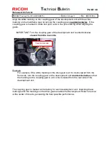
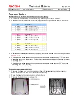
3. Remove the bottom cover. (screw x6)
Bottom cover


