V-C3 Training
263
Slide 263
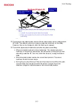
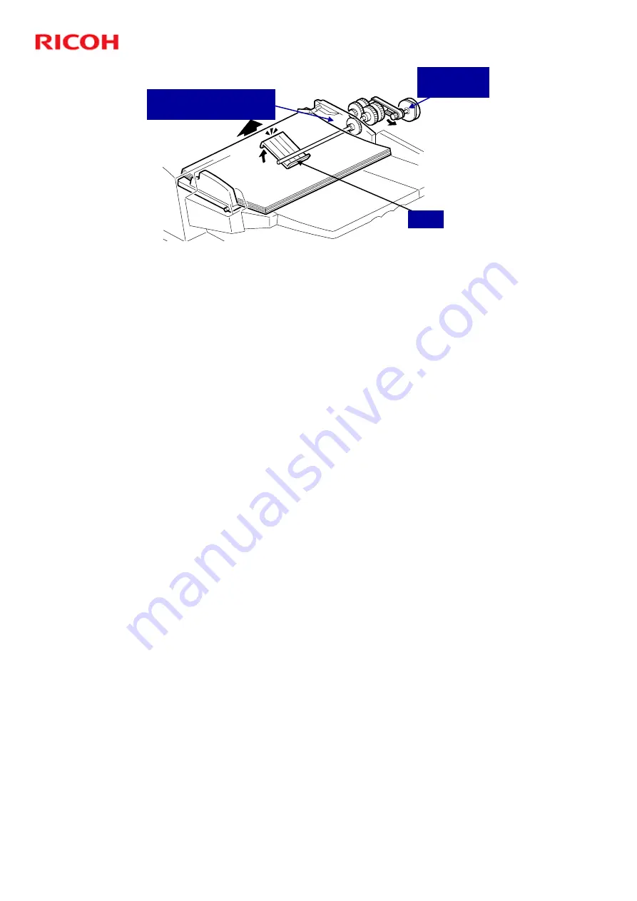
Bottom Plate Lift
!
The bottom plate lift motor lifts the bottom plate at the following
times:
"
Just after the original set sensor detects an original
"
When some originals have been fed, and the top of the stack
needs lifting
Bottom Plate
Lift Motor
Bottom Plate Lift Sensor
(in this area)
Lever
#
The timing for the bottom plate motor to lift the bottom plate can be changed with
SP 6900. The default is when an original is detected (as shown on the slide).
However, this can be changed to after the Start key is pressed.
#
The bottom plate sensor determines whether the plate needs lifting.
$
When an original is placed on the original tray: The original set sensor
switches on, the pick-up roller drops, and the sensor (on the pick-up roller
assembly) switches off. Then, the motor lifts the lever, raising the bottom
plate.
$
When the bottom plate reaches the correct feed position: The sensor
switches off and the motor stops.
$
During the job, when the top of the stack becomes too low: When the pick-
up roller drops low enough to switch the sensor on again, the motor
switches on again to raise the stack to the correct feed position.
Summary of Contents for V-C3
Page 9: ...V C3 Training 9 Slide 9 Product Overview Overview of the Machine No additional notes...
Page 15: ...V C3 Training 15 Slide 15 Product Overview Features No additional notes...
Page 30: ...V C3 Training 30 Slide 30 Product Overview Options No additional notes...
Page 118: ...V C3 Training 118 Slide 118 Installation Paper Feed Options No additional notes...
Page 124: ...V C3 Training 124 Slide 124 Installing Finishing Options Overview No additional notes...
Page 158: ...V C3 Training 158 Slide 158 Installation Connectivity Options No additional notes...
Page 191: ...V C3 Training 191 Slide 191 Machine Component Overview Machine Layout No additional notes...
Page 205: ...V C3 Training 205 Slide 205 Machine Component Overview Heaters No additional notes...
Page 210: ...V C3 Training 210 Slide 210 Controller Box Four fans No additional notes...
Page 211: ...V C3 Training 211 Slide 211 Scanner One fan No additional notes...
Page 219: ...V C3 Training 219 Slide 219 Paper Exit One fan No additional notes...
Page 220: ...V C3 Training 220 Slide 220 Duplex Unit The duplex unit has three fans No additional notes...
Page 244: ...V C3 Training 244 Slide 244 Behind the Left Lower Cover AC Drive Board No additional notes...
Page 316: ...V C3 Training 316 Slide 316 PCUs Overview No additional notes...
Page 319: ...V C3 Training 319 Slide 319 PCUs Drum Units No additional notes...
Page 335: ...V C3 Training 335 Slide 335 PCUs Development Units No additional notes...
Page 398: ...V C3 Training 398 Slide 398 Process Control When is it done No additional notes...
Page 403: ...V C3 Training 403 Slide 403 Toner Supply Control No additional notes...
Page 432: ...V C3 Training 432 Slide 432 Tray Positioning This is the same for all three trays...
Page 442: ...V C3 Training 442 Slide 442 Transfer Overview No additional notes...
Page 444: ...V C3 Training 444 Slide 444 Transfer Image Transfer Belt ITB No additional notes...
Page 452: ...V C3 Training 452 Slide 452 Transfer Paper Transfer Roller PTR No additional notes...
Page 458: ...V C3 Training 458 Slide 458 Transfer Power Supply No additional notes...
Page 462: ...V C3 Training 462 Slide 462 Transfer Paper Separation No additional notes...
Page 464: ...V C3 Training 464 Slide 464 Practical Work PTR Unit No additional notes...
Page 466: ...V C3 Training 466 Slide 466 Practical Work ITB Unit No additional notes...
Page 478: ...V C3 Training 478 Slide 478 V C3 TRAINING COPIER ENGINE FUSING No additional notes...
Page 479: ...V C3 Training 479 Slide 479 Fusing Unit Mechanisms No additional notes...
Page 491: ...V C3 Training 491 Slide 491 Fusing Unit Replacement Procedures No additional notes...
Page 509: ...V C3 Training 509 Slide 509 Exit No additional notes...
Page 514: ...V C3 Training 514 Slide 514 Inverter Duplex Tray No additional notes...

