
Summary of Contents for PolyDrive RPD 506 Series
Page 36: ......
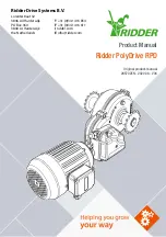
The Ridder Drive Systems PolyDrive RPD 506 Series offers smart and efficient motor control for various industrial applications. To learn more about the features and functions of this product, download the free Product Manual from 88.208.23.73:8080 and unleash the full potential of your machinery.
Page 36: ......


