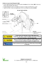
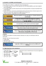
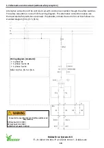


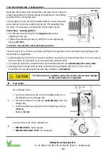


7.2.6 Connection nuts - Locking system
Read the information and instructions and obey them! They are
always applicable (in commissioning procedures) to the locking
position of the connection nuts.
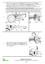
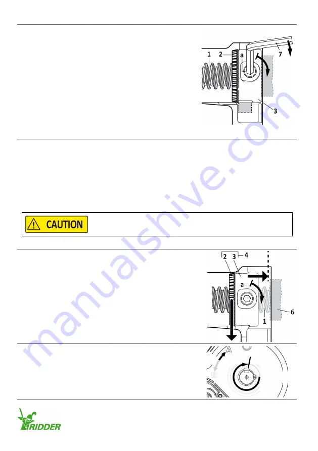
The connection nuts, on the threaded shaft (1), have two parts.
A knurled nut (2) and an adjusting ring (3). The adjusting ring
(3) must, if in operation, be locked to the knurled nut (2).
Instructions - Locking position
•
Put the hex wrench (7) with the
longest end
into the
adjusting screw (a).
•
Tighten the adjusting screw (a) with the correct tightening
torque (
0.5 Nm
).
0.5 Nm
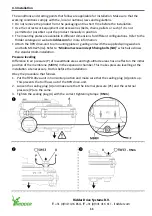
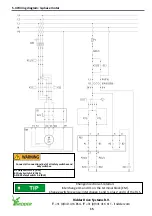
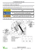
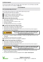
7.3 Check - Connections and functional operation
For the check, of a correct connection and functional operation, the conditions and starting points
that follow are applicable:
•
Check sequence: The check of the limit switches can be from A to B
or
from B to A. In this manual
first the check of limit switch A is done and then limit switch B
•
§7.3 and §7.4 (check and adjustment) are recommended to do
immediately after each other
•
Starting point is a fully and correctly connected wiring diagram (§5.4, §5.5, §5.6 or §5.7).
Connection of all safety switches and duty switches is
mandatory
.
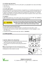
u
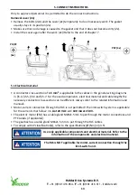
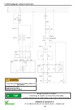
Description
1
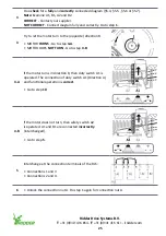
Do as follows for A.
•
Turn the knurled nut (2), on the threaded shaft (1), in
the direction of the stopper (6).
•
Put the connection nut (4) at a
small distance
from the
stopper (6).
•
Lock the adjusting ring (3) with the adjusting screw (a)
(
0.5 Nm
).
Refer to
§7.2.6!
2
Let the motor turn to the direction A.
•
MOTOR STOPS
- Go to step
4
.
•
MOTOR DOES NOT STOP
- Go to step
3
.
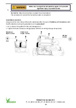
Put the system in a position where the motor cannot cause damage
to the system when it is operated.
Ridder Drive Systems B.V.
T
+31 (0)341 416 854 -
F
+31 (0)341 416 611 -
I
24
Summary of Contents for PolyDrive RPD 506 Series
Page 36: ......


