


u
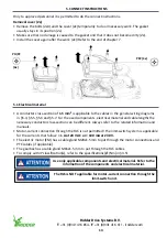
Description
1
•
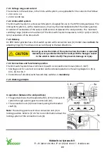
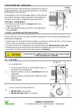
Let the system turn to an end position (A or B).
Do not go farther than the limit positions of the system when
the motor is operated. This prevents damage or injury!
2
Of the related limit switch (A or B):
•
Turn the knurled nut (2), on the threaded shaft (1), in
the direction of the stopper (6).
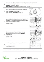
•
Tighten the knurled nut (2) with your hand against the
stopper (6).
3
•
Turn the adjusting ring (3) in the opposite direction
of the knurled nut (2). The duty switch (A1 or B1) is
operated by the switching cam (8) and switching spring
(5).
•
Hold the adjusting ring (3) at this position and go to step
4.
4
•
Lock the adjusting ring (3) with the adjusting screw (a)
(
0.5 Nm
).
Refer to
§7.2.6!
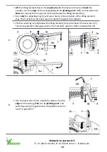
Go to step 5 to adjust the opposite end position (A or B).
Go to step 7 if the two end positions are adjusted.
Ridder Drive Systems B.V.
T
+31 (0)341 416 854 -
F
+31 (0)341 416 611 -
I
27
Summary of Contents for PolyDrive RPD 506 Series
Page 36: ......


