ENG
Page 4
233-Truck-20K-ISM-RevB-07-06-18
Mounting the suspension to the frame
Refer to the engineering drawing for the range of ride
heights available as well as spacing and clearance
requirements of the suspension.
The RSS-233 20K Truck Suspension is shipped fully
assembled. If the suspension system is taken apart
for installation, the components must be reassembled
with the proper torque applied (Appendix).
Bolt-On Installation Procedure
Suspension hangers are attached to the vehicle frame
with six 5/8-inch Grade 8 bolts in each hanger. Air
spring mounting brackets require two 5/8-inch Grade
8 bolts in each bracket. Flanged lock nuts or lock nuts
with hardened washers are required.
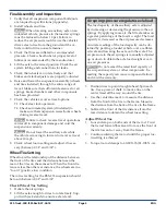
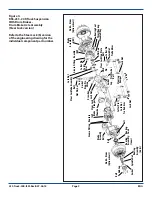
•
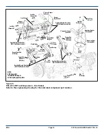
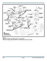
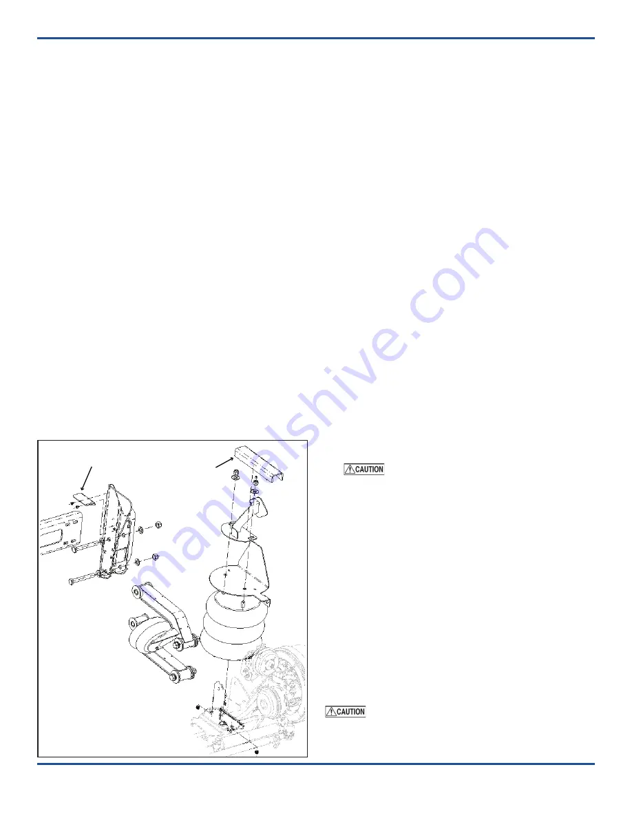
Hanger locator flanges are pre-installed to
match the ride height set by the air spring
mounting plate.
Ride height is adjusted by installing a 1” or 2”
spacer on the air spring mounting plates. The
hanger locator flange is moved up or down on
the hanger to match the height of the air spring
mounting plate and spacer installation.
• A 2” spacer kit for both the hangers and air
spring mounting plates is available for the 233-
20K disc brake and roll-off configurations.
1. Measure the vehicle frame width and the hanger-
to-hanger inside dimensions of the suspension.
Customer-supplied filler plates are required for
the hangers and air spring mounting brackets if
the vehicle frame width is narrower than that of
the suspension.
2. Place the suspension (with hanger and air spring
filler plates and the appropriate spacer(s), if re
-
quired) in the desired location.
NOTE: A crossmember must be located on the
frame within six inches of the leading or trailing
edge of the hanger.
3. Check that the location provides adequate clear-
ance for suspension components. Make sure the
top of the hangers and air spring mounting plates
are parallel to the chassis frame to maintain the
proper caster angle.
4. Hangers and air spring mounting plates should
be perpendicular to the chassis frame and in
alignment with each other. Clamp the hangers,
mounting plates, and spacer and filler plates (if
required) firmly in place.
5. Refer to the engineering drawing for the recom-
mended bolt hole locations on the hangers and
air spring mounting plates. If it is not possible to
use the recommended bolt locations, space the
bolt holes as far apart as possible to provide the
greatest support for the suspension.
Check to make sure that wires, hoses or
other components located within the frame rail
are not affected by drilling.
6. Center punch and drill six bolt holes in each
hanger. Bolt the hangers to the frame with the
recommended Grade 8 bolts and lock nuts.
7. Center punch and drill two bolt holes in each
air spring mounting bracket. Bolt the air spring
brackets to the frame with the recommended
Grade 8 bolts and lock nuts.
8. Install/connect the air control kit (ACK) to the
suspension (Page 6). Check the air system after
installation for leaks and proper operation of
controls.
9.
Perform final assembly and inspection and check
the wheel toe setting (Page 5)
Failure to torque bolts/nuts of suspension
components to specifications can result in failure of
the suspension and void the warranty.
NOTE:
Air Spring Spacer
must be used
if hanger locator flange
is moved from
factory pre-set
ride height
Hanger Locator Flange-(RH)
Flanged Screw (Self-Tapping)
2” Spacer
(Air Spring)


