background image

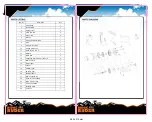
ItemNo.

Description

Qty

1

ClutchKnob

1

2

JunctionPlate

1

3

HexagonNut

2

4

AcornNutM6

2

5

washerM6

2

6

Bushing

1

7

CorrugatedWasherΦ25

1

8

Drum

1

9

Springfortheclutch

1

10

Splinedclutchshaft

1

11

ColumnarPinΦ2.5

1

12

PullRod

1

13

BraceRod

2

14

CrossheadNut(ColorZinc)M5x12

2

15

Gearboxcover

1

16

Outputgear

1

17

washer

1

18

Planetarygear

1

19

48Teethgear

1

20

Motorassembly

1

21

Gearboxassembly

1

22

Wiredcontrolassembly

1

23

Rope4.8mmx12M

1

24

AluminumFairlead

1

25

MountingPlate

1

26

1/4"Hook

1

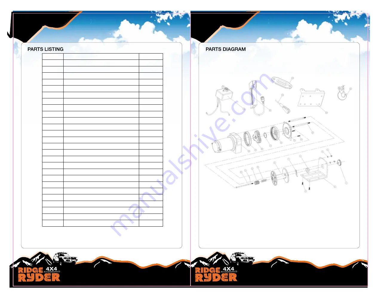
PartslistP30001AW

280 x 215mm

Summary of Contents for 341685

Page 1: ...280 x 215mm ...

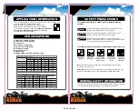
Page 2: ...2250 1020 11 2 3 4 3 1800 816 18 8 5 7 4 1440 653 28 8 5 5 1150 521 38 11 5 6 950 430 44 5 13 5 1 2 APPLICATION INFORMATION SPECIFICATIONS This winch is designed to move a load at ground level or up an incline It is neither designed nor intended for hoisting This winch is not to be used to lift or move people This winch is for intermittent use due to heat build up characteristics of various compon...

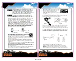
Page 3: ...drum Figure 6 This can jam the winch rope in the winch causing damage to the rope or the winch Figure 3 1 Maximum working load capacity is on the winch rope layer closest to the drum DO NOT OVERLOAD DO NOT ATTEMPT PROLONGED PULLS AT HEAVY LOADS Overloads can damage the winch and or the winch rope and create unsafe operating conditions FOR LOADS OVER 1 2 RATED CAPACITY WE RECOMMEND THE USE OF THE O...

Page 4: ...he winch mounting location does not significantly reduce ground clearance Caution INSTALLATION Figure 7 6 Underwind Overwind Step 1 Mount the winch to a firm base Be sure that your structural support is strong enough to support the rated pulling forces of the winch Step 2 While mounting is at your discretion always remember that your winch is to be operated with the winch rope in an underwound ori...

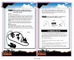
Page 5: ...rol Engaged Free Figure 9 CAUTION If the winch motor stalls do not continue to apply power 1 2 Step 3 Refer to Figure 8 for wiring diagram Route the short red and black colour coded wires from the control box to the motor Route the long red and black colour coded wires from the control box to the battery Attach the circuit breaker to battery end of the red wire Wrap the circuit breaker with electr...

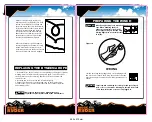
Page 6: ...ace the winch rope with the identical replacement part recommended by the manufacturer Warning PREPARING THE WINCH Wear heavy leather gloves when handling dyneema winch rope When handling the hook always use handsaver see Fig 10 Never put your fingers into the hook Placing finger s in hook could result in injury Danger 10 Figure 10 1 When anchoring the pulling vehicle set the parking brake and blo...

Page 7: ... pulling could overload the winch rope and the load could break the winch Warning 12 Figure 13 WINCHING 1 Winch with at least five wraps of winch rope around the winch drum With fewer wraps the winch rope could pull loose from the drum under load 2 When pulling a load place a blanket jacket or damper over the winch rope near the hook end see Fig 12 This will slow the snap back of a broken winch ro...

Page 8: ...ity 14 Figure 16 Figure 17 Anchor Point Tree Trunk Protector Tree Trunk Protector SNATCH BLOCK RIGGING 1 Never handle the winch rope or rigging while anyone else is at the control switch 2 Run the winch intermittently to take up winch rope slack When using a pulley block be sure the winch rope is running properly in all pulleys before applying a load Take your time when rigging and include a reaso...

Page 9: ...sion and clean as required 4 Check and clean connections 5 Replace or repair motor SNATCH BLOCK 16 MAINTAINNENCE TROUBLE SHOOTING 1 Periodically check the tightness of mounting bolts and electrical connections Remove all dirt or corrosion and always keep clean 2 Do not attempt to disassemble the gear box Repairs should be done by the manufacturer or an authorized repair center 3 The gear box has b...

Page 10: ...Splined clutch shaft 1 11 Columnar Pin Φ 2 5 1 12 Pull Rod 1 13 Brace Rod 2 14 Crosshead Nut Color Zinc M5 x 12 2 15 Gear box cover 1 16 Out put gear 1 17 washer 1 18 Planetary gear 1 19 48 Teeth gear 1 20 Motor assembly 1 21 Gear box assembly 1 22 Wired control assembly 1 23 Rope 4 8mm x 12M 1 24 Aluminum Fairlead 1 25 Mounting Plate 1 26 1 4 Hook 1 Parts list P3000 1AW 280 x 215mm ...

Reviews: