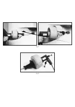
HINT! If your cable tool/retriever bulb has hooked onto a solid blockage such
as a rag or ball of hair, it may be wise to pull the cable out of the drain by hand.
Reversing the cable to retrieve it may cause the blockage to unscrew off the
cable.
The only adjustment on the Autofeed is the round top adjustment screw under
the feed actuator lever. Its purpose is to adjust the distance the feed actuator
lever has to be depressed to engage the different size cables. Turn knob
clockwise to accommodate the larger 3/8" cable, and turn knob counter
clockwise to accommodate the 5/16" cable. No adjustment is necessary direct
from the factory.
Maintenance of Autofeed unit
A drop of grease to the following areas once a month will extend the life of the
Autofeed unit and keep it well maintained:
a. Top of large top adjustment screw
b. Threads on bottom of top adjustment screw
c. Outside diameter of top roller holder housing
There are no grease fittings to worry about, however, the Autofeed will
accumulate dirt, grease and debris over time. It is a good idea to periodically
remove the Autofeed unit from the nose piece and clean with cleaning solvent
and a firm brush.
It is also a good idea to apply spray lubricant, once a week, to the Autofeed
roller bearing surface. This will extend the life of the bearings and keep them
free to operate properly.
MAINTENANCE
1. Cables should be thoroughly flushed with water after each use to prevent
damaging effects of drain cleaning compounds. Periodically lubricate
Cables and couplings with oil.
Cables should be replaced when they become severely corroded or worn.
Warning: All repairs, electrical or mechanical, should be attempted only by
trained repairmen. Contact the nearest RIDGID factory authorised repair
centre. Use only RIDGID replacement parts, any other may create a hazard.
LUBRICATION INSTRUCTIONS
Monthly
Periodic disassembly for cleaning and lubricating will assure long trouble-
free service for your RIDGID/KOLLMAN K-39/K-39B Drain Cleaner.
1. Disassemble unit
A. Unscrew Nose Piece. Thread is a normal right hand thread. If necessary,
insert smooth round rod into hole in O.D. of Nose Piece to “break loose”
thread.
B. Pull off Hand Grip Assembly.
C. Remove four Springs. The two Clamp Springs attach to Canister front half
in a manner similar to a pegboard hook.
2. Thoroughly clean all parts. If required, use emery cloth to remove rust
and/or scale from inside of Sleeve.
3. Coat Springs and inside of Sleeve with good quality graphite based grease
and reassemble.
K-39B
ELECTRICAL SAFETY
1. 230 Volts present at charger terminals. Do not probe with conductive
objects, due to risk of electric shock.
2. Charge only RIDGID No. 72-BP rechargeable batteries, other types of
batteries may burst causing personal injury and damage.
3. If battery case is cracked do not insert in charger, due to risk of electrical
shock.
4. Shorting of battery terminal may cause sparks of burns.
5. No user servicable parts inside the power unit, battery pack or charger.
Refer all repairs to an Authorized Service Center or other competent repair
service. Servicemen: Disconnect charger plug from power source before
servicing.
6. Do not operate charger if it has received a sharp blow, been dropped, or
otherwise damaged in any way.
7. Do not disassemble charger; take it to a qualified serviceman when service
is required. Incorrect reassembly may result in electric shock or fire.
8. Do not expose charger to rain or snow.
9. Battery explodes in fire. Do not burn batteries for any reason.
10.Do not charge tool in damp or wet environment.
11.Use of an attachment not recommended or sold by RIDGID may result in
a risk of fire, electric shock, or injury to persons.
12.Charge battery pack in temperatures above +40
°
F (4
°
C) and below +105
°
F
(41
°
C). This is important and will prevent serious damage to the batteries.
13.Store tool & battery pack in locations where temperatures will not exceed
120
°
F (49
°
C).
14.Battery leakage may occur under extreme usage or temperature condi
tions. If liquid comes in contact with skin, wash quickly with soap and
water, then with lemon juice or vinegar. If liquid gets in your eyes, flush
them with clean water for a minimum of 10 minutes and seek immediate
medical attention.
15.To prevent damage to tool, do not remove battery pack from tool while it’s
running.
16.To reduce risk of damage to electric plug and cord, pull by plug rather than
cord when disconnecting charger.
17.Make sure cord is located so that it will not be stepped on, tripped over,
or otherwise subjected to damage or stress.
18.Do not operate charger with damaged cord or plug, have them replaced
immediately.
BATTERY CHARGER
Charging Procedure
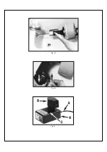
With your thumb, lift up latch and withdraw battery pack unit from tool handle
(Fig.14). Plug charger cord (Fig. 15A) into standard 230 Volt outlet, then
insert battery pack into charger (Fig. 15B). After plugging cord into outlet and
inserting battery pack into charger, the charger’s red light (Fig. 15C) will turn
“ON”. This indicates the battery pack is receiving a fast charge. When light
turns off the battery pack is fully charged and in a trickle charge mode.
Important Charging Notes
The battery pack accepts only about 80% of its maximum charge capacity
with its first charge; or, after prolonged storage it will also require additional
time on the first charge. However, after several charge and discharge cycles,
the batteries should be up to full charge capacity and delivering maximum
performance.
If Batteries Do Not Charge Properly
1. Check for voltage at outlet by plugging in some other electrical device.
2. Check to see if outlet is connected to a light switch which turns power off
when lights are turned off.
3. Check battery pack terminals for dirt. Clean with cotton swab and alcohol
if necessary.
DANGER: 230 Volts present at charger terminals. Do not touch charger
terminals due to risk of electrical shock.
4. If you still do not get proper charging, take or send both tool and charger
to your local RIDGID Authorized Service Center.
Summary of Contents for 23513
Page 1: ...K 39 K 39B K 40 Kollmann ...
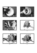
Page 8: ...Fig 1 Fig 2 Fig 5 Fig 4 Fig 3 Fig 6 ...
Page 9: ...Fig 8 Fig 9 Fig 10 Fig 7 ...
Page 10: ...Fig 11 Fig 12 A B ...
Page 11: ...Fig 13 Fig 15 Fig 14 ...


