background image

SeeSnake

®

FlatPack and Color FlatPack

Record Serial Number below and retain product serial number which is located on nameplate.

Serial No.

Kollmann

SeeSnake

®

FlatPack 

and Color FlatPack

SeeSnake

®

Diagnostic Equipment

Test Equipment Depot - 800.517.8431 - 99 Washington Street Melrose, MA 02176

FAX 781.665.0780 - TestEquipmentDepot.com 

99 Washington Street 
Melrose, MA 02176 

Phone 781-665-1400

Toll Free 1-800-517-8431

Visit us at www.TestEquipmentDepot.com

Summary of Contents for Color FlatPack

Page 1: ...late Serial No Kollmann SeeSnake FlatPack and Color FlatPack SeeSnake Diagnostic Equipment Test Equipment Depot 800 517 8431 99 Washington Street Melrose MA 02176 FAX 781 665 0780 TestEquipmentDepot com 99 Washington Street Melrose MA 02176 Phone 781 665 1400 Toll Free 1 800 517 8431 Visit us at www TestEquipmentDepot com ...

Page 2: ...ration Equipment Set Up 7 Connections 7 Operation 8 Video Recording 8 At the Job Site 9 Transportation Storage 10 Centering Guides 11 Installing the SeeSnake Star Type Centering Guides 11 Installing Star Type Centering Guides 11 Removing Star Type Centering Guides 12 Installing the SeeSnake Compact and FlatPack Ball Type Centering Guides 12 Maintenance and Cleaning Preventative Maintenance 13 Came...

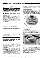
Page 3: ...d loss of power Reduce the risk of electrical shock Keep all elec trical connections dry and off the ground Do not touch plug with wet hands Battery Precautions Use only the size and type of battery specified Be sure to install the battery with the correct po larity as indicated in the battery compartment Recharge batteries with charging units specified by the battery manufacturer Using an imprope...

Page 4: ... Allows for better control of the tool Store tools in dry shaded place Such measures re duce the risk of electrical shock Protect against lightning For added protection for this product during a lightning storm or when it is left unattended and unused for long periods of time unplug it from the wall outlet This will prevent damage to the product due to lightning and power surges Protect against ex...

Page 5: ...oxes or receptacles Do not operate the system with electrical compo nents removed Exposure to internal parts increases the risk of injury Do not place the unit in water Water entering the housings will increase the risk of electrical shock Do not use the unit as a chair or table Dropping or shocking the unit can result in damage to the unit which increases the risk of electrical shock If used on a...

Page 6: ...NLY turn the connector s outer locking sleeve Bending or twisting the connector body inside the locking sleeve will damage the connector 3 Monitor Pack Camera Control Unit CCU The Monitor Pack is a camera control unit CCU that provides power to the camera reel control of the cam era s light intensity and a built in monitor for viewing the image The Monitor Pack Figure 3 may be powered by either a ...

Page 7: ...h S O S 3 short 3 long 3 short pattern in Morse Code no video signal from the camera head WHITE Steady Flashing In Line transmitter is active RED Rapid Flashing slowing from 8 to 4 flashes 2 flashes 1 flash While pushing the red multi function button indicates changes to the brightness level of the camera s LED lighting Table 1 Figure 7 LED Indicators SeeSnake FlatPack and Color FlatPack Kollmann ...

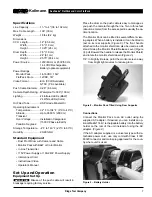
Page 8: ...se only cord with Class II IEC 60320 connector and mains plug approved for the coun try where unit is used Figure 9 Battery Holder Specifications Line Capacity 11 2 to 4 38 to 102 mm Max Cable Length 100 30 m Weight 18 lbs 8 2 kg Dimensions CCU Length 14 35 6 cm Width 7 5 19 cm Height 10 25 26 cm Drum Depth 7 5 19 cm Width 24 61 cm Height 25 75 65 4 cm Power Source 120V 60 Hz or 230V 50 Hz 14 4 VD...

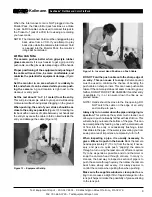
Page 9: ...ck to make sure the monitor s power switch is turned ON To turn the system OFF press and quickly release the multi function button Put the camera head into the access point and adjust the camera s lighting if necessary To adjust the camera s lighting press and hold the red multi function button After about four seconds the red LED indicator on the Monitor Pack will begin flashing rapidly This indi...

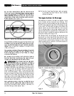
Page 10: ...st be used to minimize the chance of bending the push cable on sharp corners This can cause push cable failure If the camera just does not seem to want to go any farther DO NOT FORCE THE CAMERA If another entry is available try it or run water down the line as ex plained below NOTE Hands should be close to the line opening DO NOT catch the cable on the edge of an entry and continue to push Always ...

Page 11: ...f the system remove the camera from the pipe or enclosed environment and let the camera head cool for 10 to 15 minutes Running water into the line will also help cool the camera head Always use the minimum illumination required to maximize picture quality and to avoid excessive heat build up Ask customers what is in the line or what the line is used for prior to putting the camera into the line Av...

Page 12: ...g your inspection Move the guide back a little and the camera head may bias downward when you push and upward as you pull back This could help you see the top and bottom of larger pipes more easily Two centering guides will tend to keep the camera head aimed toward the center of the pipe allowing you to see more of the pipe at once Centering guides should be pre stressed prior to use for increased...

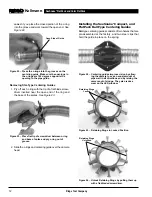
Page 13: ...screwdriver between c ring and base of spike and pry c ring out of groove 2 Slide the c rings and centering guide over the camera head Installing the SeeSnake Compact and FlatPack Ball Type Centering Guides Ball type centering guides consists of two halves that are pre assembled at the factory and two steel clips that hold the guide in place on the spring Figure 24 Centering guides improve vision ...

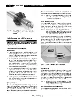
Page 14: ...r on these components Stir in a bucket of warm water and mild detergent to flush the spring area NOTE Never use a water jetter to clean the spring as sembly If a spring takes a set during storage dip it in hot water to straighten Push Cable and Drum The push cable and drum require almost no mainte nance It is important however to keep the push cable clean to spot any excessive cuts or abrasions wh...

Page 15: ...uld be taken to a RIDGID Independent Authorized Service Center or returned to the factory All repairs made by Ridge service facilities are warranted against defects in material and workmanship Test Equipment Depot 800 517 8431 99 Washington Street Melrose MA 02176 FAX 781 665 0780 TestEquipmentDepot com ...

Reviews: