SeeSnake Diagnostic Equipment
Kollmann
4
exits the pack through a video out jack to the monitor
y o u
h a v e
c h o -
s e n
t
o
use.
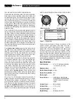
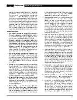
Figure 1 – Connectors
There are several pairs of these connectors in the
system: camera - push cable, push cable - hub, hub -
interconnect cable, interconnect cable - monitor/
power pack. The above designations are always true
for these connectors. Guide pins are always a differ-
ent color than circuit pins, and guide sockets are a dif-
ferent size than the other sockets. Align guide pins to
guide sockets, ensuring the remaining pins and sock-
ets are aligned, and push straight together. To unplug,
pull straight out. Wiggle the connector a little, if neces-
sary, but DO NOT bend or twist it!
Specifications
Line Capacity:..............2
″
to 10
″
(all pipe materials,
i.e. cast iron, pvc, etc.)
Maximum Run:.............325
′
Reel & Frame Weight:...43 lbs.
Reel & Frame Width: ...15
″
Reel Length:................30
″
Power Source: .............120V/60 Hz, 230V/50 Hz
(Converted to approximately
12V DC current to camera
head)
Camera Type:...............Monochrome
Camera Size:................1.75
″
x 2.12
″
Camera Weight: ...........4 oz.
Depth Rating:...............Waterproof to 330
′
tors, and push rod are built for long lasting use.
The system can be broken down into four sub-assem-
blies: camera head, reel/dolly, interconnect cable, and
monitor/power pack. The monitor/power pack is pow-
ered by any 120 volt AC source (or 230 volt). In turn,
they convert this power to ~12 volt DC to power the
camera head and LED lighting, as well as any options
in the system. Other than the controls found on the
monitor/power pack for such things as brightness,
contrast, and LED lighting, the system has no external
buttons or dials.
The 12 volts DC for the camera (and options) is fed to
the reel through the interconnect cable that is stored on
the dolly. There are three conductors within this cable
that terminate to pins (male) and sockets (female) in
the connectors. See Figure 1 for a detailed description.
Pins/sockets #1 and #2 are the supply and return for
the 12 volts DC. Pins/sockets #3 are the return path for
the video signal generated by the camera back to the
monitor/ power pack. The connectors on this cable are
the same type that are found at the camera head, push
cable, and any options.
The interconnect cable plugs into the back side of
the reel into an area called the hub. Inside the hub,
there is a device called a slip ring, a kind of rotating
electrical joint. The slip ring allows the reel to spin
without twisting the cables that enter/exit the reel,
while allowing power and video signals to pass.
The push cable is connected to the slip ring by anoth-
er connector inside the reel, on the cone-shaped por-
tion. This is the “dry end” of the push cable. The
power and video signals travel within the push cable
to and from the camera head. At the “wet end” of the
push cable, a transition occurs from the stiff rod to a
flexible coil cord within the
SPRING
. This cord has
another connector that is held into the back of the
camera with a locking sleeve. There are also two
stainless steel safety cables within the spring which
prevent the spring from overstretching when pulling
the camera from pipe.
Once the 12 volt DC power enters the camera, it
passes through a circuit board that directs it to either
the actual video module, or the lights. There is also
some protective circuitry to minimize electronic failure.
The camera circuitry processes images it receives
through the sapphire window and converts it to a
standard video signal that returns to your monitor for
display. If you have a separate power pack, this signal
Pin/Socket
Function
1 ..........................Neutral
2 ..........................+12 VDC
3 ..........................Video Signal
Male Connector
Female Connector
Guide
#1
#3
#2
Guide
#1
#3
#2


