background image

17

MAINTENANCE

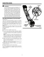
Fig. 23

WARNING: 

The  saw  mounting  brackets  are  designed  to  fit 
snugly over the table edges with locking levers in 
the open position. With the locking levers in the 
lowered (locked) position, you should not be able 
to slide the saw mounting bracket assembly along 
the table edges or remove the bracket assembly 
from the table edges. If the saw mounting brackets 
will not fit over the edges, or if the brackets can 
be removed from the edges when the levers are 
locked, remove bracket assembly immediately and 
adjust bracket adjustment screw. Failure to heed 
this warning may result in serious personal injury.

SAW MOUNTING BRACKET ADJUSTMENT

See Figure 23.

If the saw and bracket assembly can slide over the table 
edges or be removed from the table edges when the levers 
are  locked,  the  bracket  adjustment  screws  need  to  be 
tightened. If the saw and bracket assembly will not fit over 
both table edges, the bracket adjustment screw needs to 
be loosened.

NOTE: 

The  saw  should  be  removed  from  the  mounting 

brackets before attempting to tighten or loosen the bracket 
adjustment screws.

To adjust:

 

Use a wrench to slightly loosen the nut.

 

Turn  the  screw  with  a  phillips  screwdriver.  Rotate 
clockwise if the bracket assembly needs to be tightened 
or  counterclockwise  if  the  assembly  needs  to  be 
loosened.


NOTE:

 If locking lever on saw mounting bracket cannot 

easily  be  pushed  down  into  the  closed  position,  the 
adjustment screw is too tight. Do not force locking lever 
into the closed position. Loosen the adjustment screw.

 

Install  the  bracket  on  the  front  table  edge  then  lower 
bracket to allow the rear clamp of the bracket to seat 
fully over the rear table edge.

  NOTE:

 The mounting bracket should fit snugly over the 

table edges when in the open position.

  When  the  correct  position  is  achieved,  wrench-tighten 

the nut to secure. 

 

Repeat with the second mounting bracket.

To purchase additional saw mounting bracket assemblies 
(part  no.  900510802),  call  RIDGID  customer  service  at 
1-866-539-1710.

SAW 

MOUNTING 

BRACKET

SCREWDRIVER

WRENCH

NUT

BRACKET 

ADJUSTMENT 

SCREW

SCREWDRIVER 

ACCESS HOLE

Summary of Contents for AC9944

Page 1: ...tor safety When properly cared for it will give you years of rugged trouble free performance WARNING To reduce the risk of injury the user must read and understand the operator s manual before using this product Thank you for buying a RIDGID product SAVE THIS MANUAL FOR FUTURE REFERENCE OPERATOR S MANUAL MITER SAW UTILITY VEHICLE AC9944 ...

Page 2: ...ration 14 15 Maintenance 16 17 Warranty 19 Parts Ordering Service 20 TABLE OF CONTENTS INTRODUCTION This product has many features for making its use more pleasant and enjoyable Safety performance and dependability have been given top priority in the design of this product making it easy to maintain and operate ...

Page 3: ...to your body Bend your knees so you can lift with your legs not your back WHEN HAULING THE WORKSTAND IN A VEHICLE securely tie it down to prevent movement and possible damage NEVER put the workstand where operators or bystanders are forced to stand with any part of their body inline with the path of the saw blade NEVER STAND ON WORKSTAND Serious injury could occur if the stand tips or you accident...

Page 4: ...elds and as necessary a full face shield when operating this product Precautions that involve your safety Wet Conditions Alert SYMBOLS The following signal words and meanings are intended to explain the levels of risk associated with this product SYMBOL SIGNAL MEANING DANGER WARNING CAUTION CAUTION Indicates an imminently hazardous situation which if not avoided will result in death or serious inj...

Page 5: ...owing tools not included are needed for assembly ADJUSTABLE WRENCH S WORK SUPPORT WORK STOP EXTENSION ARM QUICK RELEASE SAW MOUNTING BRACKETS WORK SUPPORT BRACKET TRANSPORT HANDLE LEG SUPPORT LIFT ASSIST HANDLE SUPPORT LEG Fig 2 SCREWDRIVER ...

Page 6: ...lat Washers 16 x 6 5 x 1 5 2 Plastic Washers 19 x 6 8 x 2 2 Lock Nuts M6 x 55 2 Blister Packs Saw Mounting Hardware Not Shown 2 Operator s Manual Not Shown LOOSE PARTS HEX BOLTS 2 WASHERS 2 LOCK NUTS 2 LOCK NUTS 4 WORK SUPPORTS 2 WHEELS 2 WARNING The use of attachments or accessories not listed in this manual might be hazardous and could cause serious personal injury Fig 3 SCREWS 3 TRANSPORT HANDL...

Page 7: ...or use with this product Any such alteration or modification is misuse and could result in a hazardous condition leading to possible serious personal injury WARNING Do not connect to power supply until assembly is complete Failure to comply could result in accidental starting and possible serious personal injury PREPARING THE WORKSTAND FOR ASSEMBLY See Figures 4 5 With workstand out of box and pac...

Page 8: ...vertighten ATTACHING THE LEG SUPPORTS See Figure 7 Insert leg support into wheel leg set with foot peddle side facing down toward lift assist handle Align the two holes in the leg support with the holes in the assembly Place a spring washer over the hex bolt and insert up through each leg hole Place a spring washer and lock nut over end of each bolt and secure Repeat on other side LIFT ASSIST HAND...

Page 9: ...E WORK SUPPORTS See Figure 10 The work supports support the workpiece during cutting operations To install the work supports Loosen lock lever and slide extension arm out for accessibility Position work support bracket so that the work support shaft is positioned in the center of the stand table Align large square hole in work support bracket with end of extension arm and slide bracket over rail I...

Page 10: ...ounting bracket adjustment If the saw has mounting holes that line up with the slots in the saw mounting brackets Disconnect the saw from power supply and lock the saw arm in the down position Place a 2 x 4 or similar type of stable support underneath the saw to raise the saw and allow access to the saw s mounting feet Feed a carriage bolt up through each side of the bracket and adjustment plate A...

Page 11: ...e Maintenance section of this manual Failure to heed this warning may result in serious personal injury 15 20 25 30 35 40 45 10 ASSEMBLY MOUNTING THE MITER SAW TO THE WORKSTAND See Figures 13 14 Use the handles located at the rear of the saw mounting brackets to aid in installing or removing saw and bracket assembly Lift the saw and bracket assembly allowing the assembly to tilt slightly toward yo...

Page 12: ...sp the lift assist handle Push down on lock mechanism release lever and lift workstand into raised position NOTE The workstand is heavy Get help when needed WARNING To avoid serious personal injury when lifting bend your knees so you can lift with your legs not your back CAUTION Do not lift by any part of the miter saw that is attached to the workstand Failure to heed this warning may result in po...

Page 13: ...d miter saw is mounted on the stand it may be necessary to slide the power head blade assembly forward and lock in place when going through doorways or other narrow openings Remove any workpieces clamps or other accessories from saw FOLD DOWN Move miter saw to wheel end of workstand and secure per the instructions in this manual See figure 17 Make sure extension arms and support legs are retracted...

Page 14: ...rm locking lever Extend the extension arm to the desired position Tighten the extension arm locking lever To extend the support legs Press latch at end of extension arm and pull leg outward from arm until hinge is fully exposed The leg will bend at hinge and face in a downward position Press and hold latch in middle of support leg Extend adjustment leg completely to the ground To retract extension...

Page 15: ... do not use both work support at the same time when using the work stop feature OPERATION Fig 20 HEIGHT ADJUSTMENT KNOB DISTANCE ADJUSTMENT KNOB WORK SUPPORT ADJUST WORK SUPPORT UP AND DOWN ADJUST WORK SUPPORT IN AND OUT EXTENSION ARM To adjust the work support Loosen the work support height adjustment knob Adjust the work support to the desired position Tighten the work support height adjustment ...

Page 16: ... to damage from various types of commercial solvents and may be damaged by their use Use clean cloths to remove dirt dust oil grease etc WARNING Do not at any time let brake fluids gasoline petroleum based products penetrating oils etc come in contact with plastic parts Chemicals can damage weaken or destroy plastic which may result in serious personal injury Periodically check all fasteners for t...

Page 17: ... needs to be loosened NOTE The saw should be removed from the mounting brackets before attempting to tighten or loosen the bracket adjustment screws To adjust Use a wrench to slightly loosen the nut Turn the screw with a phillips screwdriver Rotate clockwise if the bracket assembly needs to be tightened or counterclockwise if the assembly needs to be loosened NOTE If locking lever on saw mounting ...

Page 18: ...18 NOTES ...

Page 19: ... at www ridgid com When requesting warranty service you must present the original dated sales receipt The authorized service center will repair any faulty workmanship and either repair or replace any part covered under the warranty at our option at no charge to you One World Technologies Inc P O Box 35 Hwy 8 Pickens SC 29671 RIDGID HAND HELD AND STATIONARY POWER TOOL 3 YEAR LIMITED SERVICE WARRANT...

Page 20: ...d service center nearest you please call 1 866 539 1710 or visit us online at www ridgid com The model number of this product is found on a plate attached to the bottom of the table Please record the serial number in the space provided below When ordering repair parts always give the following information Model No Serial No AC9944 987000 043 1 11 07 REV 01 OPERATOR S MANUAL MITER SAW UTILITY VEHIC...

Reviews: