9
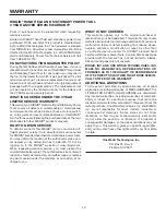
Fig. 10
ASSEMBLY
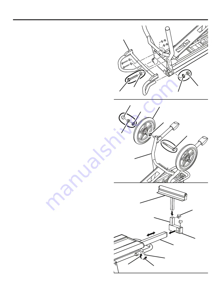
ATTACHING THE TRANSPORT HANDLE
See Figure 8.
Align transport handle ends with holes in stand table end
caps and insert.
Place a spring washer over the screw and insert screw
through each hole of the handle and leg support
bracket.
Place a washer and lock nut over the end of each screw
and secure.
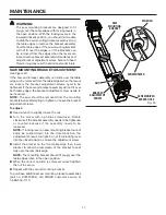
ATTACHING THE WHEELS
See Figure 9.
Insert bolt through wheel leg set.
Place washer and then wheel over bolt.
Place washer and lock nut over end of bolt and secure.
Do not overtighten.
Place end cap over lock nut.
Repeat on other side.
After wheels are installed and all previous assembly
procedures have been followed, workstand may be turned
over to rest on its legs.
NOTE:
The workstand is heavy. Get help when needed.
INSTALLING THE WORK SUPPORTS
See Figure 10.
The work supports support the workpiece during cutting
operations.
To install the work supports:
Loosen lock lever and slide extension arm out for
accessibility.
Position work support bracket so that the work support
shaft is positioned in the center of the stand table.
Align large square hole in work support bracket with end
of extension arm and slide bracket over rail.
Insert the work support in shaft of bracket.
Insert adjustment knob through knob hole in shaft of
bracket and tighten to secure into position.
Insert adjustment knob through knob hole on top of
bracket and tighten to secure into position.
Repeat on the other side.
Ensure workstand is stable and can be opened and
locked.
Fig. 8
TRANSPORT
HANDLE
LOCK NUT
WASHER
SCREW
HEX BOLT
WHEEL
WASHER
LOCK NUT
LEG
ASSEMBLY
Fig. 9
WORK
SUPPORT
WORK
SUPPORT
BRACKET
LOOSEN
TIGHTEN
LOCK LEVER
EXTENSION
ARM
ADJUSTMENT
KNOB
SHAFT
WASHER
END CAP
SPRING
WASHER
Summary of Contents for AC9944
Page 18: ...18 NOTES ...


