background image

6

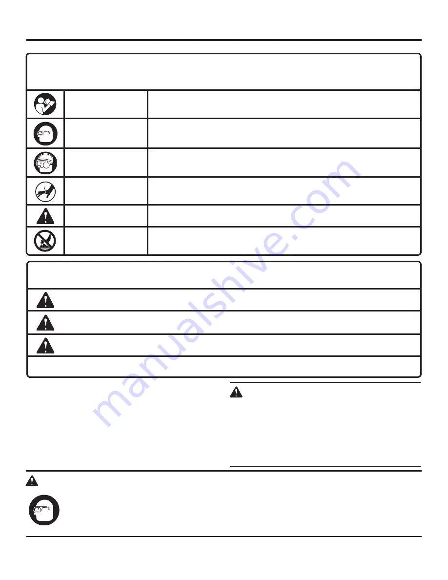
SYMBOLS

Some of the following symbols may be used on this tool. Please study them and learn their meaning. Proper interpreta-
tion of these symbols will allow you to operate the tool better and safer.

SYMBOL 

NAME 

DESIGNATION/EXPLANATION

The following signal words and meanings are intended to explain the levels of risk associated with this product. 


SYMBOL   SIGNAL 

MEANING

Read The Operator’s 
Manual

To reduce the risk of injury, user must read and understand operator’s manual 
before using this product

Eye Protection

Always wear safety goggles or safety glasses with side shields and, as necessary, 
a full face shield when operating this product.

Eye, Ear and Head  
Protection

Always wear other personal protective equipment such as hearing protection 
and a hard hat when needed.

Keep Hands Away

Keep hands and body away from the discharge area of the tool.

Safety Alert

Precautions that involve your safety.

Hot Surface

To reduce the risk of injury or damage, avoid contact with any hot surface.

DANGER:

Indicates an imminently hazardous situation, which, if not avoided, will result in death or 
serious injury.

WARNING:

Indicates a potentially hazardous situation, which, if not avoided, could result in death or 
serious injury.

CAUTION:

Indicates a potentially hazardous situation, which, if not avoided, may result in minor or 
moderate injury

CAUTION:

(Without Safety Alert Symbol) Indicates a situation that may result in property damage.

SERVICE

Servicing requires extreme care and knowledge and should 
be  performed  only  by  a  qualified  service  technician.  For 
service we suggest you return the product to your nearest 
AUTHORIZED SERVICE CENTER for repair. When servic-
ing, use only identical replacement parts.

WARNING:

To avoid serious personal injury, do not attempt 
to use this product until you read thoroughly and 
understand  completely  the  operator’s  manual. 
If  you  do  not  understand  the  warnings  and 
instructions in the operator’s manual, do not use 
this  product.  Call  RIDGID

®

  customer  service  for 

assistance.

The operation of any power tool can result in foreign objects being thrown into your eyes, which can result 
in severe eye damage. Before beginning power tool operation, always wear safety goggles or safety glasses 
with side shields and, when needed, a full face shield. We recommend Wide Vision Safety Mask for use 
over eyeglasses or standard safety glasses with side shields. Always use eye protection which is marked 
to comply with ANSI Z87..

WARNING:

SAVE THESE INSTRUCTIONS

Summary of Contents for R138BNA

Page 1: ...afety When properly cared for it will give you years of rugged trouble free performance WARNING To reduce the risk of injury the user must read and understand the operator s manual before using this product Thank you for buying a RIDGID product SAVE THIS MANUAL FOR FUTURE REFERENCE OPERATOR S MANUAL 18 GAUGE BRAD NAILER r138bna ...

Page 2: ...ntenance 17 18 Accessories 19 Troubleshooting 19 Warranty 21 Customer Service Information Back page TABLE OF CONTENTS INTRODUCTION This tool has many features for making its use more pleasant and enjoyable Safety performance and dependability have been given top priority in the design of this product making it easy to maintain and operate ...

Page 3: ... caught in moving parts Keep fingers away from trigger when not driving fasten ers to avoid accidental firing Do not overreach Keep proper footing and balance at all times Proper footing and balance enables better control of the tool in unexpected situations Use safety equipment Always wear eye protection Dust mask nonskid safety shoes hard hat or hearing protection must be used for appropriate co...

Page 4: ...ched Do not operate this tool if it does not contain a legible warning label Do not continue to use a tool that leaks air or does not function properly SPECIFIC SAFETY RULES operation Always assume that the tool contains fasteners Do not carry the tool from place to place holding the trigger Accidental discharge could result Always handle the tool with care Respect the tool as a working implement ...

Page 5: ...ausing injury or death Do not use with an air compressor which can po tentially exceed 200 psi as tool may burst possibly causing injury The connector on the tool must not hold pressure when air supply is disconnected If an incorrect fitting is used the tool can remain charged with air after discon necting and thus will be able to drive a fastener even after the air line is disconnected possibly c...

Page 6: ...ly hazardous situation which if not avoided could result in death or serious injury CAUTION Indicates a potentially hazardous situation which if not avoided may result in minor or moderate injury CAUTION Without Safety Alert Symbol Indicates a situation that may result in property damage SERVICE Servicing requires extreme care and knowledge and should be performed only by a qualified service techn...

Page 7: ...ng control and the operating controls can be activated in any sequence to actuate the tool Additional actuation can occur when any operating control is released and re activated Air inlet port In an air tool the opening to which the compressed air supply is connected usually by means of a threaded fitting Fastener A staple pin brad nail or other fastening device which is designed and manufactured ...

Page 8: ...Air Consumption 0 046 ft3 cycle at 100 psi Air Inlet 1 4 in NPT Weighted sound impulse power level 86 9 dBA Emission sound pressure level 73 9 dBA Vibration 2 28 m s2 Weight 2 6 lbs no mar pad side loading magazine QUICK CONNECT SWIVEL CONNECTOR DEPTH OF DRIVE ADJUSTMENT ADJUSTABLE EXHAUST selectablE trigger workpiece contact Belt Hook latch reload indicator jam release ...

Page 9: ...ncreased comfort and control of the tool quick connect swivel connector The quick connect swivel connector helps prevent hose tangles RELOAD INDICATOR The reload indicator shows whether the magazine is running low on fasteners SELECTable TRIGGER The selectable trigger lets the operator choose between Contact Actuation for higher productivity and Single Sequential Actuation for precise fastener pla...

Page 10: ...pply before leaving the work area moving the tool to another location or handing the tool to another person Failure to do so could result in serious personal injury WARNING Always wear eye protection Eye protection does not fit all operators in the same way Make sure the eye protection chosen has side shields or provides protection from flying debris both from the front and sides APPLICATIONS You ...

Page 11: ... down and away from the nose To replace the pad fit it into place over the nose and push up to reseat On board storage for the pad is located on the magazine of the tool An extra no mar pad is provided in the on board storage area ADJUSTing the EXHAUST See Figure 3 The adjustable exhaust on the end cap of the tool allows the operator to direct the exhaust according to operator prefer ence To adjus...

Page 12: ...The tool and air hose must have a hose coupling that allows all pressure to be removed from the tool when the coupling is disconnected WARNING Always use a coupling that discharges all the compressed air in the tool at the time the fitting or hose coupling is disconnected Using a coupling that does not discharge the compressed air could cause unintended operation and serious personal injury Fig 4 ...

Page 13: ...magazine open WARNING Keep the tool pointed away from yourself and others when loading nails Failure to do so could result in possible serious personal injury Feed a strip of brad nails into the magazine Be sure the nail heads are pointed upward the tips are pointed downward and the tips rest against the bottom of the magazine Push the magazine cover closed until it securely snaps into place Fig 5...

Page 14: ...he trigger lever pivot pin WARNING The nailer will not function properly if the selector is not securely seated in either position A or B Always assure the selector is seated properly to avoid an unexpected fastener discharge and possible serious personal injury Reconnect the tool to the air supply Grip the tool firmly to maintain control Position the nose of the tool onto the work surface Push th...

Page 15: ...o determine the required depth for the application To determine depth of drive first adjust the air pressure and drive a test nail To achieve the desired depth use the drive depth adjustment on the tool Disconnect the tool from the air supply Remove fasteners from the tool Turn the depth selector left or right to change the driving depth Reconnect the tool to the air supply Load the tool with fast...

Page 16: ...t the air hose and keep the tool pointed away from you while clearing the jam Open magazine and remove fasteners from the tool Pull up on the latch and open the jam release Insert a flat blade screwdriver into the driving mechanism and push the driver mechanism back freeing the fastener jam Remove the bent fastener Close the jam release and latch Reconnect the tool to the air supply Reinstall fast...

Page 17: ...nd below freezing the moisture in the air line may freeze and prevent tool operation We recommend the use of air tool lubricant or permanent antifreeze ethylene glycol as a cold weather lubricant CAUTION Do not store tools in a cold weather environment to prevent frost or ice formation on the tools operating valves and mechanisms that could cause tool failure NOTE Some commercial air line drying l...

Page 18: ... trigger in this position for a minimum of 5 seconds The tool must not oper ate Press the workpiece contact firmly against the workpiece Pull the trigger The tool must operate With the workpiece contact still depressed release the trigger The driver must return to its up position Rotate the selectable trigger knob on the trigger to Contact Actuation operation Position B as shown in figure 12 With ...

Page 19: ... fasteners Damaged fasteners Loose magazine or nose screws Dirty magazine Worn or damaged driver Verify that fasteners are the correct size Replace fasteners Tighten screws Clean magazine Install Driver Maintenance Kit ACCESSORIES To order parts and maintenance kits call 1 866 539 1710 Overhaul Maintenance Kit 079001001701 Driver Maintenance Kit 079001001702 Driver Assembly Kit 079001001703 Trigge...

Page 20: ...20 NOTES ...

Page 21: ...ervice center will repair any faulty workmanship and either repair or replace any part covered under the warranty at our option at no charge to you One World Technologies Inc P O Box 35 Hwy 8 Pickens SC 29671 WHAT IS NOT COVERED This warranty applies only to the original purchaser at retail and may not be transferred This warranty only covers de fects arising under normal usage and does not cover ...

Page 22: ... location of the authorized service center nearest you please call 1 866 539 1710 or visit us online at www ridgid com The model number of this tool is found on a plate attached to the magazine cover of the tool Please record the serial number in the space provided below When ordering repair parts always give the following information Model No Serial No R138BNA OPERATOR S MANUAL 18 GAUGE BRAD NAIL...

Reviews: