background image

6

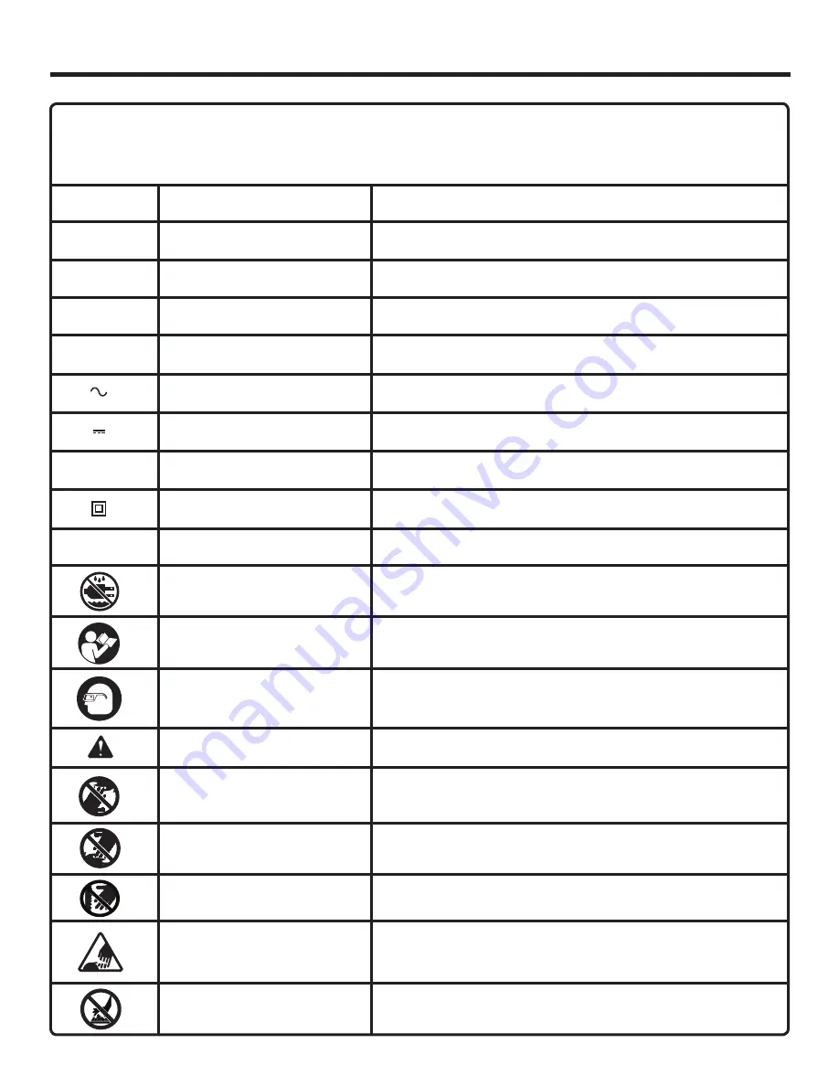
SYMBOLS

Some of the following symbols may be used on this tool. Please study them and learn their meaning. Proper interpreta-
tion of these symbols will allow you to operate the tool better and safer.

Read The Operator’s Manual

Safety Alert 

No Hands Symbol

No Hands Symbol

No Hands Symbol

No Hands Symbol

SYMBOL 

NAME 

DESIGNATION/EXPLANATION

Voltage

Current

Frequency (cycles per second)

Power

Time

Type of current

Type or a characteristic of current

Rotational speed, at no load

Double-insulated construction

Revolutions, strokes, surface speed, orbits etc., per minute

Do not expose to rain or use in damp locations.

To reduce the risk of injury, user must read and understand 
operator’s manual before using this product.

Eye Protection

Always wear safety goggles or safety glasses with side shields 
and a full face shield when operating this product.

Precautions that involve your safety.

Failure to keep your hands away from the blade will result in 
serious personal injury.

Failure to keep your hands away from the blade will result in 
serious personal injury.

Failure to keep your hands away from the blade will result in 
serious personal injury.

Failure to keep your hands away from the blade will result in 
serious personal injury.

Wet Conditions Alert

.../min

Per Minute

Class II Construction

no

No Load Speed

Direct Current

Alternating Current

min

Minutes

W

Watt

Hz

Hertz

A

Amperes

V

Volts

Hot Surface

To reduce the risk of injury or damage, avoid contact with 
any hot surface.

Summary of Contents for R82320

Page 1: ...y When properly cared for it will give you years of rugged trouble free performance WARNING To reduce the risk of injury the user must read and understand the operator s manual before using this produ...

Page 2: ...ssembly 9 n Operation 10 13 n Maintenance 14 n Warranty 15 n Customer Service Information 16 TABLE OF CONTENTS INTRODUCTION This tool has many features for making its use more pleasant and enjoyable S...

Page 3: ...er control of the tool in unexpected situations n Use safety equipment Always wear eye protection Dust mask non skid safety shoes hard hat or hearing protection must be used for appropriate conditions...

Page 4: ...this rule will reduce the risk of electric shock fire or serious personal injury n Do not place battery tools or their batteries near fire or heat This will reduce the risk of explosion and possibly...

Page 5: ...ug of extension cord are the same number size and shape as those of plug on charger b That extension cord is properly wired and in good electrical condition and c That wire size is large enough for AC...

Page 6: ...jury user must read and understand operator s manual before using this product Eye Protection Always wear safety goggles or safety glasses with side shields and a full face shield when operating this...

Page 7: ...e product to your nearest AUTHORIZED SERVICE CENTER for repair When servic ing use only identical replacement parts WARNING To avoid serious personal injury do not attempt to use this product until yo...

Page 8: ...ariable Speed No Load Speed 0 2850 min Blows Per Minute 0 2800 BPM Charger Input 120 V 60 Hz AC only Charge Rate 20 minutes Torque Maximum 1400 in lb Fig 1 COUPLER SWITCH TRIGGER BATTERY PACK 4 1 8 in...

Page 9: ...bit rotation after the operator releases the switch trigger CHARGER The charger has a key hole hanging feature for convenient space saving storage Screws should be installed so that the center distan...

Page 10: ...r supply n Attach the battery pack to the charger by aligning the raised ribs on the battery pack with the grooves in the charger then slide the battery pack onto the charger n After normal usage 20 m...

Page 11: ...3 Fig 3 POWER INDICATOR EVALUATE INDICATOR CHARGING INDICATOR FULL INDICATOR LED INDICATOR BATTERY PACK RED LED GREEN LED ACTION Power Evaluate Evaluate Evaluate Evaluate Charging Full Without batter...

Page 12: ...the driver n Remove driver bit from the coupler CAUTION The impact driver is not designed to be used as a drill BIT Fig 4 1 2 3 PULL COUPLER FORWARD INSERT BIT RELEASE COUPLER COUPLER RAISED RIBS LAT...

Page 13: ...operating condition Therefore switch should always be locked when not in use or carrying at your side Fig 8 Fig 7 SWITCH TRIGGER FORWARD REVERSE DRIVING OR REMOVING SCREWS See Figures 8 9 n Place the...

Page 14: ...e doing The batteries in this tool have been designed to provide maximum trouble free life However like all batteries they will eventually wear out Do not disassemble battery pack and attempt to repla...

Page 15: ...www ridgid com When requesting warranty service you must present the original dated sales receipt The authorized service center will re pair any faulty workmanship and either repair or replace any par...

Page 16: ...e location of the authorized service center nearest you please call 1 866 539 1710 or visit us online at www ridgid com The model number of this tool is found on a plate attached to the motor housing...

Reviews: