


ARTIST m – Instalation Guide 2.3 – 12.06.2003
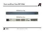
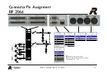
24
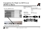
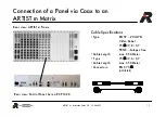
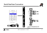
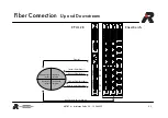
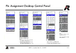
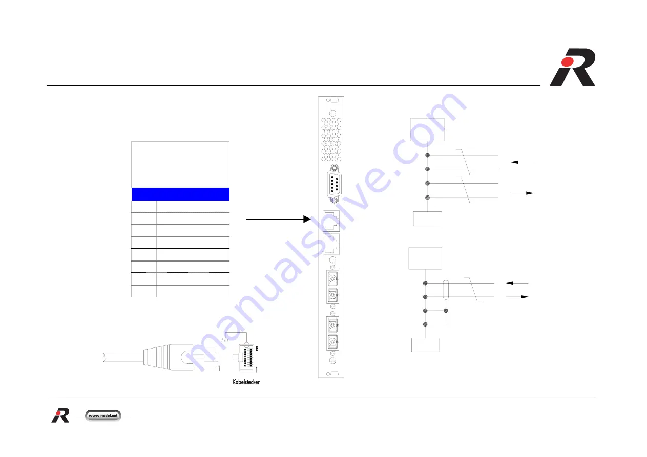
Serial Interface Connection
RJ
45
RJ45
1
S9
D
OWN
STREAM
UP
STR
EAM
CPU-128
10
/1
00
B
T
SE
RI
A
L
AL
AR
M
Pin Signal
1
RxD + (RS422)
2
RxD — (RS422)
3
TxD + (RS422)
4
RxD (RS232)
5
GND (RS232)
6
TxD — (RS422)
7
TXD (RS232)
8
GND
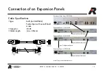
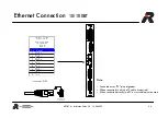
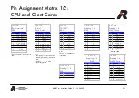
"CPU-128"
"Serial Interface"
RJ45
Serial
RS422
RJ45
TxD +
RxD +
TxD —
RxD —
1
2
3
6
Serial
RS232
RJ45
GND
RxD
GND
TxD
4
7
5
8
*
Connector: RJ45
* This port is normally used only for service
purposes and is not required during normal
operation.


