24
1200 Series SmartPanels 1.0 User Manual
0
1
-0
0
0
H
B
0
3
E
G
-A1
0
4.2
Ports / Pinouts
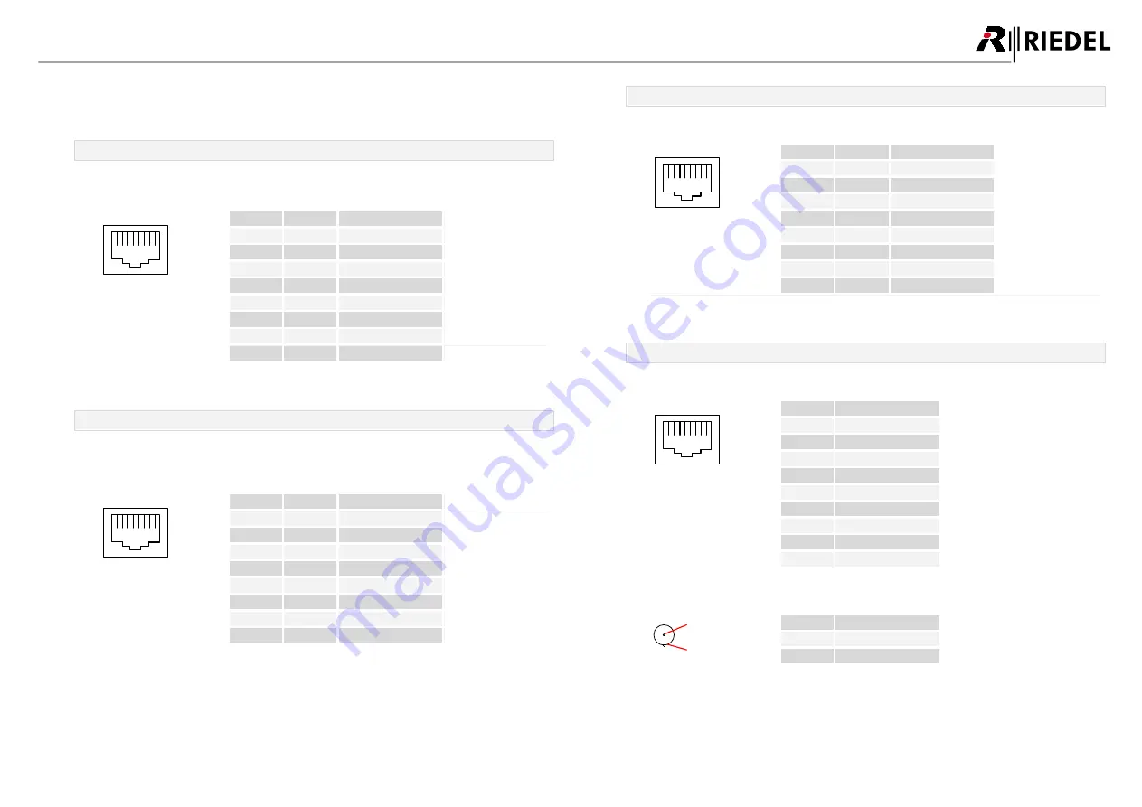
In this chapter the Ports/Pinouts of the RSP-1232HL are shown.
Ethernet port
The Ethernet connectors are used to connect an intercom network (AES67).
This port is 1000Base-T compatible.
1
8
Pin
Signal
Standard color
1
BI_DA+
orange/white
2
BI_DA-
orange
3
BI_DB+
green/white
4
BI_DC+
blue
5
BI_DC-
blue/white
6
BI_DB-
green
7
BI_DD+
brown/white
8
BI_DD-
brown
figure 39: ETH connector RJ-45 pinout (8P8C)
Management port
The Management connector is currently not used. In future this port is used to configure the panel
over a network that is separated from the intercom network. This port is 100Base-T compatible.
1
8
Pin
Signal
Standard color
1
TX+
orange/white
2
TX-
orange
3
RX+
green/white
4
--
blue
5
--
blue/white
6
RX-
green
7
--
brown/white
8
--
brown
figure 40: MGNT connector RJ-45 pinout (8P8C)
Expansion port
The Expansion connector is used to connect Expansion Panels.
1
8
Pin
Signal
Standard color
1
TX+
orange/white
2
TX-
orange
3
RX+
green/white
4
--
blue
5
--
blue/white
6
RX-
green
7
--
brown/white
8
--
brown
figure 41: Expansion connector RJ-45 pinout (8P8C)
Matrix connectors
The Matrix connectors are used for the connection to the intercom matrix (AES3).
1
8
Pin
Matrix 1
1
TxD +
2
TxD -
3
RxD +
4
--
5
--
6
RxD -
7
--
8
--
Chassis
Chassis GND
figure 42: Matrix 1 connector RJ-45 pinout
2
1
Pin
Matrix 2
1
TxRx Data +
2
TxRx Data -
figure 43: Matrix 2 connector BNC pinout


