background image

Rieju chassis

35

Chassis

EN

G

LI

S

H


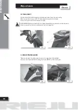
16. SHOCK ABSORBER

* Remove the seat, the front lateral covers, the rear cowlings and the filter box.
Unscrew the 2 bolts (A/F -29) that hold the shock absorber onto the chassis.
Then, remove it from the back.

ATTENTION: Before disassembly, hold the chassis by the lower part in order to avoid the 
fall of the swing arm and the wheel.

ATTENTION: Pay attention to the shock absorber position for the later assembly.

17. GEAR LEVER 

Unscrew the fixing  bolt (A/F -30).
After, pull carefully the lever in order not to damage the grooved shaft.

A

B

F-29

F-30

Summary of Contents for MRX-SMX 50

Page 1: ...MRX SMX 50 MRX SMX 50 C h a s s i s w o r k s h o p m a n u a l ...

Page 2: ...ECIFICATIONS UNPACKING APPARANCE DATA FOR IDENTIFICATION ANTI TAMPERING LABEL IDENTIFYING THE MAIN ELEMENTS CONTROLS KEYS STEERING LOCK SIDE STAND INSTRUMENT PANEL TYRES CHECKING TYRE PRESSURES FUEL TANK COOLANT REPLACING COOLANT ENGINE OIL TRANSMISSION OIL BRAKE FLUID ADJUSTING THE MINIMUM REV SETTING ADJUSTING TRANSMISION CHAIN TENSION 6 7 8 9 10 15 15 18 18 18 18 19 20 20 20 20 21 22 22 22 23 2...

Page 3: ...HEADLIGHT 15 FRONT INDICATOR LIGHTS 16 REAR LIGHT 17 REAR INDICATOR LIGHTS 18 INSTRUMENT PANEL 19 TURN INDICATOR REGULATOR 20 CONTACT RELAY 21 CONTROL UNIT CDI 22 BATTERY 23 OIL SENSOR 24 OIL TANK 25 AIR FILTER 26 FUEL TRANSMISSION OIL MIXER 27 AIS SYSTEM 28 EXHAUST 29 SILENCER 30 RADIATOR 31 CARBURETTOR 32 GEAR CHANGE LEVER 33 REAR BRAKE LEVER 34 SIDE STAND 28 28 29 29 30 30 30 31 31 32 32 33 33 ...

Page 4: ... ENGINE 38 REAR WHEEL 39 CHAIN PROTECTOR 40 DRIVE CHAIN 41 SHOCK ABSORBER 42 SWING ARM 43 FRONT WHEEL 44 FRONT BRAKE CALLIPER 45 FRONT BRAKE DISK 46 SPEED SENSOR 47 FRONT FOOTRESTS 48 REAR FOOTRESTS BRACKETW 48 TIGHTENING TORQUES 43 43 44 45 45 45 46 46 47 47 47 48 48 48 49 ...

Page 5: ...Introducción Chassis 4 ...

Page 6: ...5 ENG Introduction Introduction ...

Page 7: ...y simply result in disagreeable complaints N B Rieju S A reserves the right to make changes at any time without prior notification For any enquiry or for further complimentary information please call the Rieju S A After sales Service MANUAL UPDATES Updates will be sent within a reasonable period of time Each new CD Rom will update previous information The contents list will be updated if the modif...

Page 8: ...hazard RISK OF EXPLOSION Indicates operations which may constitute a risk of explosion TOXIC Indicates a possibility of intoxication or inflammation of the upper respiratory tract MECHANICAL MAINTENANCE Operations to be performed only by an expert mechanic ELECTRICAL MAINTENANCE Operations be performed only by an expert electrical electronic technician NO Operations to be absolutely avoided SERVIC...

Page 9: ...d Letters not follo wed by a number indicate a single screw In case of different screws being referred to in the illustration the letter Tr is followed by a number and a small letter for instance Tr4a Unless otherwise specified units and components are reassembled by pro ceeding in the reverse order of removal F Pr Tr P Ap S Es T Tr Figure Tightening torque Page Paragraph Section Diagram Table Scr...

Page 10: ... end box wrenches by pulling and not pushing Adjustable wrenches F 1 should only be used in case of emergency i e when a properly sized wrench is not available They should preferably not be used as the movable jaw tends to open thus risking damaging or not properly tightening the bolt to the correct torque In any case when using an adjustable wrench take care to proceed as shown in Figure 1 Except...

Page 11: ...refer to the final torque which must be attained progressively by steps Loosen and tighten aluminium alloy parts covers only after the engine has fully cooled down Only use screwdrivers with sizes suitable to the screws to be loosened or tightened Work in a comfortable position and ensure that the vehicle is stable Never use a screwdriver as a lever or chisel Never use pincers to loosen or tighten...

Page 12: ...clean the vehicle components Never suck from or blow into the fuel pipe When welding make sure that there are no flammable liquids in the vicinity Always re move the tank even if completely empty and disconnect the negative cable from the battery Never leave the engine running in closed or poorly ventilated areas Before any servicing make sure that the motorbike is perfectly stable The front wheel...

Page 13: ......

Page 14: ...13 ENG Getting to know the motorbike Getting to know the motorbike ...

Page 15: ......

Page 16: ...and chassis nut control plastics Electrical system checking Segments wear control Radiator water level control Exhaust system checking Oil pump operation checking Change Dimensions Overall length Overall width Overall height Seat height Wheelbase Minimum ground clearance 2050 mm 790 mm 1170 mm 920 mm 1332 mm 358 mm Weight Dry 93 kg Engine Type Transmission Make Cylinder arrangement Cylinder capaci...

Page 17: ...Clutch type Wet multiple disc Primary transmission Clutch crown wheel Drive pinion Transmission ratio Z 71 Z 20 1 3 55 Secondary transmission Engine output pinion Drag plate Transmission ratio Chain Z 11 Z 52 1 4 36 420 x 126 steps Speed 1ª 2ª 3ª 4ª 5ª 6ª Primary shaft Z 12 Z 16 Z 19 Z 22 Z 24 Z 25 Secondary shaft Z 36 Z 33 Z 29 Z 27 Z 25 Z 24 Gear ratio 1 3 00 1 2 06 1 1 53 1 1 23 1 1 04 1 0 96 O...

Page 18: ...isc Ø 260 mm Disc Ø 200 mm Tyres Front Rear MRX MRX PRO 80 90 21 con cámara 1 7 kg cm2 110 80 18 con cámara 1 8 kg cm2 Brakes Front Rear MRX PRO SMX PRO Wave type Disc Ø 260 mm Wave type Disc Ø 200 mm Tyres Front Rear SMX SMX PRO 100 80 17 con cámara 1 8 kg cm2 130 70 17 con cámara 1 9 kg cm2 Electric equipment Ignition system Generator Ignition advance Electronic 12V 95W Ducati 20º 1 4 mm before ...

Page 19: ...r The data for identifying the engine A F 1 are on the right sump Vehicle identification number The identification number of the motorcycle B F 2 is stamped on the steering pipe This identification number is used to identify the moped F 1 F 2 B A F 3 C C SAFETYTAG It contains the identification data of the motor cycle according to the 97 24 CE guidelines It is absolutely essential to indicate the ...

Page 20: ...PARTS Left side 1 Headlight 2 Oil mixing tank 3 Battery SMX 4 Gear pedal IDENTIFICATION OFTHE MAIN PARTS Right side 5 Radiator 6 Tool box 7 Fuel tank cap 8 Rear brake pedal 9 Passenger footrest 10 Number plate light and plate holder 1 2 4 3 10 7 5 8 9 6 F 4 F 5 ...

Page 21: ...The motorcycle is provided with two numeric code keys which allow To establish start ignition To turn on the lights To lock the steering STEERING LOCK Activate With the handlebar turned to the left get the key thorough into the lock and then turn it to the left Deactivate Turn the key to the right SIDE STAND Make sure that the side stand is well fixed and it moves correctly likewise it is advisabl...

Page 22: ...rning light This warning light lits when the temperature of the coolant is too much high If this happens stop the engine immediately N neutral gear warning light This warning light lits when the transmission is in the neutral gear position Oil level warning light This warning light lits when the oil level is low Warning light of the full beam headlights This indicator lits when the full beam headl...

Page 23: ...ted with the tyres at room tem perature FUELTANK Unscrew the cap and refuel the tank paying attention not to pass the limit A F 11 if after filling some petrol residues are showed on the motorcycle wipe them off immediately Use normal unleaded petrol with a RESEARCH 95 octane number Fuel tank capacity Total 8 4 litres ENDURO SUPERMOTARD FRONT REAR 1 7 kg cm2 1 8 kg cm2 FRONT REAR 1 8 kg cm2 1 9 kg...

Page 24: ...l should fill the radiator panel 3 If the level is low add coolant 4 Put the cap again COOLANT REPLACEMENT Before carrying out this operation place a tray under the tube 1 Parking the vehicle on a flat surface and place a tray under the radiator 2 Drain the cooling circuit removing the drain plug A F 13 In case you need more coolant than usual to reach the indicated level or if you need to refill ...

Page 25: ...e up for some minutes 3 Pull the engine up Place a tray for the oil under the engine and remove the drain plug C F 15 4 Unscrew the drain screw A F 15 and the screw B F 15 to allow the oil to flow 5 The drain screw tightly A F 15 6 Fill the engine with oil till it comes out by the level hole B F 15 Put the screw again in the hole B F 15 place the drain plug C F 15 and tighten it It is advisable to...

Page 26: ...ty of the used liquid should comply with the specified regulations since otherwise the rubber gaskets can wear causing leaks and reducing the effectiveness of the brake Recommended brake fluid DOT 4 F 18 A Start the engine and warm it up for some mi nutes in the 1000 to 2000 rpm interval spee ding up till the 4000 to 5000 rpm When the engine responds quickly to the acceleration that means it is ho...

Page 27: ...and screw in or unscrew the adjacent bolts and nuts B F 21 always getting the same distan ce on both sides of the axle A wrong alignment of the chain and the wheel can make the chain comes out as well as give stability problems in the motorcycle F 19 F 20 B F 21 To control and adjust the chain you should operate on the rear axle of the wheel always working in the maximum tension point of the chain...

Page 28: ...27 ENG Disassembly Disassembly ...

Page 29: ...off the back and pull it backwards to remove it from the front catch 2 REAR LATERAL COVERS Remove the seat Unscrew the 3 bolts A F 3 Following pull the part to remove it A 3 PILLION SEAT Remove the seat and the rear cowlings Unscrew the 2 bolts A F 4 holding the 2 nuts B F 5 of the lower part A A B F 1 F 2 F 3 F 4 F 5 ...

Page 30: ...ront 5 MUFFLER Remove the seat and the left rear cowling Loosen the clamp A F 8 of the exhaust which holds the muffler Following unscrew the 2 bolts B F 9 that fix the muffler to the chassis To extract it pull the muffler backwards ATTENTION Before proceeding to the muffler disassembly make sure that it is cooled down A B F 6 F 7 F 8 F 9 ...

Page 31: ... that hold the exhaust onto the engine in the front part and the Silembloc bolt C F 11 Following remove the vent tube AIS system D F 12 and the exhaust pulling it forward ATTENTION Before proceeding to the muffler disassembly make sure that it is cooled down A C B 7 AIS SYSTEM SECONDARY AIRVALVE Loosen the clamps A F 13 Unscrew the 2 fixing bolts B F 13 A D B F 10 F 11 F 12 F 13 ...

Page 32: ...battery pulling it upwards 9 REARTURN SIGNALS Cut the clamp that hold the leads and disconnect them from the main wiring Following loosen the screw A F 17 and pull the lead to remove the light ATTENTION Before proceeding to the lights disassembly pay attention to the sequence of the terminals for the later assembly see electric diagram A F 14 F 15 F 16 F 17 ...

Page 33: ...r To extract it pull the lead to remove the light ATTENTION Before proceeding to the lights disassembly pay attention to the sequence of the terminals for the later assembly see electric diagram 11 REAR MUDGUARD Remove the seat the pillion seat the rear turn signals and the taillight Unscrew the 2 bolts A F 20 holding the 2 nuts B F 21 of the lower part A A B F 18 F 19 F 20 F 21 ...

Page 34: ... bolts A F 22 of the filter cover and remove the filter ATTENTION Connect the earth cable again during the assembly SMX version A B 13 REGULATOR Remove the seat and the right lateral cover Disconnect the regulator from the wiring A F 24 After unscrew the bolt B F 24 to remove it F 22 F 23 A A B F 24 F 25 ...

Page 35: ... 27 at the top After cut the clamp B F 28 that hold the nozzle of the carburettor To extract the filter box pull it backwards 14 INTERMITTENCE STATION Remove the seat and the left lateral cover Disconnect the intermittence station from the main wiring Following extract it from the rubber B A F 26 F 27 F 28 ...

Page 36: ...rber onto the chassis Then remove it from the back ATTENTION Before disassembly hold the chassis by the lower part in order to avoid the fall of the swing arm and the wheel ATTENTION Pay attention to the shock absorber position for the later assembly 17 GEAR LEVER Unscrew the fixing bolt A F 30 After pull carefully the lever in order not to damage the grooved shaft A B F 29 F 30 ...

Page 37: ... 31 and then disconnect the main wiring A 19 OILTANK Remove the seat the left front lateral cover and disconnect the level sensor wire and the oil filter Unscrew the 2 bolts A F 33 that fix the tank to the chassis and remove it ATTENTION Before disassembly empty the oil tank through the filter hole A F 31 F 32 F 33 F 34 ...

Page 38: ...ire and the oil filter Unscrew the 2 bolts that attach the tank to the chassis and remove it 21 OIL FILTER Remove the left front cover Loosen the hose clamp and the clamp that hold the filter onto the oil tank To extract it pull it outward ATTENTION Place a tray under the oil tank to collect the oil F 35 F 36 F 37 ...

Page 39: ...move the seat and the front lateral covers ATTENTION Before disassembly close the fuel cock Extract the vent tube Unscrew the 2 bolts A F 40 that fix the tank to the chassis Following remove the tank pulling it upwards A F 38 F 39 F 40 F 41 ...

Page 40: ...URETTOR Remove the seat the front cowlings and the fuel tank only move it away Cut the hose clamp that hold the carburettor onto the filter box Unscrew the top cover of the carburettor and extract it Likewise disconnect the air intake sleeve and the rest of tubes ATTENTION Pay attention to the position of the tubes for the later assembly B A F 42 F 43 F 44 ...

Page 41: ...spark plug Disconnect the thermocontact lead Disconnect the neutral gear lead located at the lower part of the engine the flywheel Magneto lead and the ECU leads Unscrew the bolts of the oil mixing cover and disconnect the transmission Empty the cooling circuit by loosening the drain screw B F 47 Disconnect the hose of the cylinder head radiator C F 47 and pump radiator Remove the 3 lock nuts and ...

Page 42: ... air intake radiator Loosen the clamps that hold the engine hoses to the radiator C F 51 After unscrew the bolt D F 52 that attach the radiator to the chassis and remove it pulling upwards A B C D 27 SIDE STAND ATTENTION Hold the motorcycle before carrying out Remove the tensioning spring A F 53 Following unscrew the nut B F 53 holding the screw on the inside B A F 49 F 50 F 51 F 52 F 53 ...

Page 43: ...e bolt holding the nut on the inside After turn the light off in the wiring ATTENTION Pay attention to the position of the leads for the later assembly 29 FRONT MUDGUARDS Unscrew the 4 bolts A F 56 located at the lower part of the mudguards F 54 F 55 F 56 A ...

Page 44: ...s cover After remove the rubber from the headlight cover and disconnect the leads ATTENTION Pay attention to the lead position for the later assembly A 31 DASHBOARD Loosen the 4 rubber clamps of the headlight cover and tilt it to facilitate the task Disconnect the odometer lead A F 60 and the LEDs leads B F 59 Following unscrew the 2 top bolts C F 61 that fix the screen to the chassis A B B F 57 F...

Page 45: ...ION For the later assembly it is advisable to repla ce the copper gaskets and drain the circuit ATTENTION Brake fluid is abrasive A B Disconnect the transmission from the clutch A F 63 and from the starter B F 63 After unscrew the 2 bolts C F 64 and remo ve the lever B A C 34 HANDLEBAR Remove the controls from each end Unscrew the 4 bolts A F 64 and remove the handlebar A 33 CLUTCH LEVER 32 FRONT ...

Page 46: ...ain the circuit A B 36 REAR BRAKE CALIPER Unscrew the join through the screw A F 66 Following unscrew the 2 bolts B F 66 that attach the caliper to the calliper bracket ATTENTION For the later assembly it is advisable to replace The copper gaskets and drain the circuit A B 35 FRONT BRAKE CALIPER 37 FRONT WHEEL ATTENTION Loosen the fixing bolt A F 67 of the axle lo cated at the fork Unscrew the whe...

Page 47: ...meter sensor B F 69 A B 39 FRONT BRAKE DISC Remove the front wheel Unscrew the bolts A F 70 that fix the disc 40 STEERING Unscrew the 4 bolts A F 71 of the handlebar Loosen the 2 lateral screws B F 71 to facilitate its removal Extract the top nut C F 71 and remove the top plate To extract the axle unscrew the nut D F 71 Para extraer el eje desenroscar la tuerca D F 71 A B C A D B F 68 F 69 F 70 F ...

Page 48: ...the bolt A F 72 holding the lower nut ATTENTION Take into account the position of the spring for the later assembly A 43 REAR BRAKE LEVER Unscrew the bolt A F 75 A 42 REAR FOOTREST Unscrew the bolt A F 74 holding the lower nut A F 72 F 73 F 74 F 75 SMX version ...

Page 49: ...IN Remove the 2 fixing screws A F 77 from the guard and take it out Extract the securing clip B F 78 of the link and remove it Chain tensioning see page 26 A B 44 DRIVE CHAIN GUARD Unscrew the 2 bolts A F 76 and remove the guard A F 76 F 77 F 78 ...

Page 50: ...an reduce the stroke when starting 46 REAR BRAKE MASTER CYLINDER Remove the rear brake master cylinder cover taking the 2 bolts out A F 79 To remove the master cylinder is necessary to disconnect the STOP switch lead B F 80 and unscrew it Remove the clamp C F 80 of the brake fluid delivery pipe and empty it in a tray A B C A ATTENTION Brake fluid is abrasive F 79 F 80 F 81 ...

Page 51: ...Rieju chassis Chassis 50 48 SWING ARM Remove the chain the rear brake caliper the rear wheel and the shock absorber Unscrew the nut A F 82 and remove the axle on the right side A F 82 ...

Page 52: ... fixing screws Handlebar control screw Shock absorber screws Fork bolt Handlebar fixing bolt Steering top nut Steering middle nut Swing arm bolt Element Kg m N m Notes 38 52 17 23 72 98 24 36 6 10 6 10 20 26 2 4 38 52 51 69 18 24 18 24 25 34 60 75 3 8 5 2 1 7 2 3 7 2 9 8 2 4 3 6 0 6 1 0 0 6 1 0 2 0 2 6 0 2 0 4 3 8 5 2 5 1 6 9 1 8 2 4 1 8 2 4 2 5 3 4 9 0 7 5 TORQUETABLE G G Grease G G G ...

Reviews: