background image

5895

9

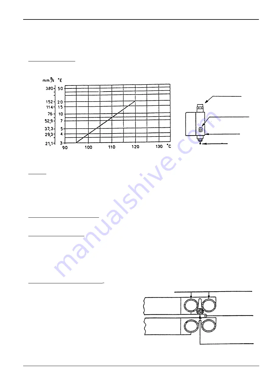
SPRAY TEMPERATURE ADJUSTMENT

Thermostats for: adjustment - maximum value - minimum value

Adjustment thermostat: it prevents the burner start up if the fuel temperature has not reached the required value for
a good spray as indicated in the diagram below.

Example: fuel oil with viscosity of 7 °E  at 50 °C is pre-heated at approximately 110 °C.

The thermostat has to be generally set at a value higher than the required one: (120° C indicated on the knob to get
approx. 100° C at the nozzles).
The value read has to be done after some minutes of performance and later the necessary adjustments could be
carried out.

Minimum value contact thermostat: it intervenes by stopping the burner if the fuel temperature decreases under the
value necessary for a good combustion.

Maximum value thermostat: it switches off the resistances when in case of failure of the adjustment thermostat, the
temperature increases inside the pre-heater.

In case of abnormal temperature, make sure of the regular functioning of control thermostat and of the resistance in
contact with the probe of the thermostat.
The thermostat is calibrated by the factory at 180° C.

IMPORTANT NOTICES

Pre-heater thermostats substitution

.

Replace the probe of the new thermostat, after the
loosening of the fixing screws of the plates pack, tak-
ing care of good contact between the probe and the
tubes and the resistance, see drawing.
Similarly for the resistance substitution.
- If during the operation exceptional changes or too

much high temperatures should be detected, verify
the continuity of the resistance, using and ohmme-
ter, contacting the temperature probe (approximate-
ly 35 Ohm).

Sheath for

thermometer

Adjusting knob

of thermostat

Pre-heater

Purge

Spray temperature

Viscosity 

a

t 50

° C

Tubes into aluminium plate

Resistance

Thermostat probe

Aluminium
plate

Summary of Contents for 3434985

Page 1: ...2915895 2 01 2009 Installation use and maintenance instructions Heavy oil burner CODE MODEL TYPE 3434985 PRESS 60 N 616 T80 3434986 PRESS 60 N 616 T80...

Page 2: ......

Page 3: ...ostat 17 Fair leads 14 Pre heater relay 18 Back pressure valve 15 Ignition transformer DIMENSIONS Thermal power Output 171 342 684 kW 15 30 60 kg h Operation Two stages Fuel Oil with max viscosity at...

Page 4: ...ly one nozzle the pressurization conditions are improved and no problems arise Minimal fuel capacity with only one nozzle 15 kg h 171 kW Note for the extended combustion head version Apply the extensi...

Page 5: ...the same level of the suction pipe In this case the foot valve is not required RING SYSTEM for heavy oil with viscosity up to 65 E 50 C 1 Tank properly heated for heavy oil 5 Forwarding pump 2 Filter...

Page 6: ...gnition transformer TB Earth of the burner TE Start up and adjustment thermostat Tm Minimum value contact thermostat TM Maximum value contact thermostat V Electromagnetic valves Tm 1 2 4 6 95 96 A2 1...

Page 7: ...for 380 V TWO STAGE OPERATION It can be achived by the thermostat connected to 14 15 wiring terminal board removing the bridge controlling 2nd valve PRE HEATER RESISTANCES CONNECTIONS D2644 220V 380V...

Page 8: ...stat fair lead Pg 13 5 4 Control thermostat fair lead Pg 13 5 5 2nd stage thermostat fair lead Pg 13 5 6 Pre sheared holes Further prospective signals or controls can be connected to the burner wiring...

Page 9: ...pump pressure or the nozzles match could be changed The pump is set by the factory at 20 bar Combustion head adjustment Turn the screw A till the set point detected from the diagram is on line with t...

Page 10: ...he first flame it is adjustable both for opening and closing 2nd STAGE Red and black levers The red lever controls the air damper position for the second flame it is adjustable both for closing and op...

Page 11: ...e resistances when in case of failure of the adjustment thermostat the temperature increases inside the pre heater In case of abnormal temperature make sure of the regular functioning of control therm...

Page 12: ...y trouble at the burner operation Supply line filter positioned on the suction line it causes the increase of the depression in the pump with the consequent flow of gas and noise Do not overcome the d...

Page 13: ...0V Lock out Extraneous light Key Off Yellow Green Red SIGNAL PROBABLE CAUSE 2 flashes The flame does not stabilise at the end of the safety time faulty photocell faulty or soiled oil valves neutral ph...

Page 14: ......

Page 15: ......

Page 16: ...RIELLO S p A I 37045 Legnago VR Tel 39 0442 630111 http www rielloburners com Subject to modifications...

Reviews: