25
ZÜNDUNG DES BRENNERS
Die Regelungen einschalten und den Schalter
1)(A) in Stellung "MAN" setzen.
Nach erfolgter Zündung den Brenner vollständig
einstellen.
BRENNEREINSTELLUNG
Für die optimale Einstellung des Brenners soll-
ten die Abgase am Kesselausgang analysiert
werden.
Die bereits vorgenommenen Einstellungen sind:
• Flammkopf;
• Stellantrieb, Nocken I - II - IV - V.
Einzustellen sind dagegen der Reihe nach:
1 - Höchstbrennerleistung;
2 - Mindestbrennerleistung;
3 - Zwischenleistungen.
1 - Höchstleistung
Die Höchstleistung ist im Regelbereich auf Seite
10 auszuwählen.
In der vorhergehenden Beschreibung ist der
Brenner auf der Mindestleistung in Betrieb
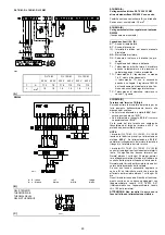
geblieben. Auf die Taste 2)(A) "+" nun drücken,
bis der Stellantrieb auf 130° geöffnet hat.
Einstellung des Düsendurchsatzes
Der Durchsatz der Düse ändert sich je nach
dem Heizöldruck im Rücklauf der Düse.
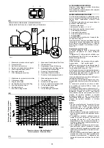
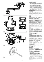
Diagramm (C) zeigt dieses Verhältnis für Ber-
gonzo Düsen Typ A3 und A4 mit 20 bar Druck
auf der Auslaßseite der Pumpe.
Diagramm (C):
Waagrechte Achse: bar, Rückschlagdruck auf
die Düse
Senkrechte Achse : kg/h, Düsendurchsatz
VERMERK
: bei 20 bar Druck im
Pumpenauslass sollte der Druck im Düsenrück-
lauf nicht mehr als 17 bar sein. Der Druckunter-
schied zwischen Pumpenauslass und
Düsenrücklauf muß mindestens 3 bar sein. Bei
kleineren Druckunterschieden kann der Druck
auf den Düsenrücklauf unbeständig sein.
Der Druckwert auf den Düsenrücklauf ist an
Manometer 1)(B) angezeigt.
Steht the Stellmotor auf Position 130°, ist der
Druck und Durchsatz der Düse maximal.
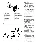
Korrekturen des Druckes im Rücklauf werden
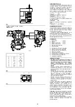
durch Veränderung des Exzenters 6)(B) und der
Schraubenmutter und Gegenmutter 4)(B) erre-
icht.
Für die Einstellung der Exzenterscheibe,
Schrauben 7) lösen, Schraube 5) drehen, bis
die gewünschte Exzentrität erreicht ist. Beim
Drehen der Schraube 5) nach rechts steigt die
Exzentrität und damit der Unterschied zwischen
max. und min. Durchsatz; beim Drehen der
Schraube 5) nach links sinkt die Exzentrität und
damit der Unterschied zwischen max. und min.
Durchsatz.
VERMERKE
• Eine gute Einstellung ist dann erreicht, wenn
die Exzenterscheibe 6) auf dem gesamten
Drehbereich des Stellmotors (20° bis 130°)
arbeitet, d.h., dass bei jeder Verstellung des
Stellmotors eine Druckänderung erfolgt.
• Niemals den Kolben zum Anschlag bringen,
der Begrenzungsring 3)(B) bestimmt den Max.
Weg.
• Nach der Einstellung von Hand prüfen, ob der
Stellmotor nach der Entriegelung (s. S. 26)
zwischen 0° und 130° kantet und ob die Mind-
est- und Höchstdruckwerte den nach Dia-
gramm (C) gewählten entsprechen.
• Zur Kontrolle des Durchsatzes im Auslass der
Düse, den Brenner öffnen, die Düse verro-
hren, den Anlauf simulieren und die Wiegung
des Brennstoffs bei min. und max. Druck
vornehmen.
• Wenn beim Höchstdurchsatz der Düse (Max.
Druck im Rücklauf) Druckschwankungen auf
dem Manometer 1) festgestellt werden, den
Druck im Rücklauf leicht verringern, bis diese
nicht mehr auftreten.
BURNER FIRING
Close load controls and set switch 1)(A) to
"MAN".
After burner firing a complete burner adjustment
should be performed.
BURNER CALIBRATION
The optimum calibration of the burner requires
an analysis of the flue gases at the boiler outlet.
The following settings that have already been
made do not require modification under normal
circumstances:
• Combustion head;
• Servomotor, cams I - II - IV - V
Contrarily, the settings listed below must be
adjusted in sequence:
1 - MAX burner output;
2 - MIN burner output;
3 - Intermediate outputs between MAX and MIN
output.
1 - MAX output
Max output of the burner must be set within the
firing rate range shown on page 10.
In the above instructions we left the burner run-
ning in MIN output operation. Now press button
2)(A) "+" until servomotor arrives at 130°.
Adjusting the nozzle flow rate
The nozzle flow rate varies according to the fuel
pressure on the nozzle return.
Diagram (C) indicates this relationship for type
A3 and A4 Bergonzo nozzles with pump delivery
pressure of 20 bars.
Diagram (C):
Horizontal axis
: bar, nozzle return pressure
Vertical axis
: kg/h, nozzle flow rate
NOTE
: with a pump delivery pressure of 20 bar,
the pressure on the nozzle return must not
exceed 17 bars.
The pressure difference between pump delivery
and nozzle return must be at least 3 bars. With
smaller pressure differences, the pressure on
the nozzle return can be unstable.
The nozzle return pressure value is indicated by
the pressure gauge 1)(B).
The output and the pressure of the nozzle are at
maximum when the servomotor is positioned on
130°.
The fine adjustment of the pressure in the return
line may be carried out by changing the setting
of the eccentric 6)(B), of the nut and lock-nut
4)(B).
The eccentric setting should be carried out by
loosening screws 7), and turning the screw 5) to
obtain the desired eccentricity. Turn clockwise
the screw 5) to increase the eccentricity,
increasing the difference between the min. and
max. capacity of the nozzle; turn counter-clock-
wise the screw 5) to decrease the eccentricity
and, consequently the difference between the
min. and max. capacity of the nozzle.
NOTE
• The proper setting of the eccentric 6) is possi-
ble when its operation field follows the servo-
motor operation field (20° … 130°): so, that
every variation of the servomotor position cor-
responds to a pressure variation.
• Do not let the piston beat repeatedly: the stop
ring 3)(B) determines the max. stroke.
• When the setting is carried out, verify manually
that no slow-down occurs between 0° and
130° and that the maximum and minimum
pressures correspond to those chosen as per
diagram (C).
• If you wish to check the delivery capacity of
the nozzle, open the burner, attach the nozzle,
simulate the start-up and then proceed with
weighing of the maximum and minimum pres-
sures of the fuel.
• If at the maximum capacity of the nozzle (max-
imum pressure in the return line) pressure fluc-
tuations are detected on the manometer 1),
slightly decrease the pressure in the return line
until they are completely eliminated.
ALLUMAGE BRULEUR
Fermer les télécommandes et mettre l'interrupt-
eur 1)(A) sur la position "MAN".
Après avoir effectué l»allumage, passer au
réglage complet du brûleur.
REGLAGE BRULEUR
Pour obtenir un réglage optimal du brûleur, il
faut effectuer l'analyse des gaz d'échappement
de la combustion à la sortie de la chaudière.
Les réglages déjà effectués qui, en principe, ne
nécessitent d»aucune modification sont:
• Tête de combustion;
• Servomoteur, cames I - II - IV - V.
Les éléments suivants doivent par contre être
réglés dans l'ordre:
1 - Puissance max. du brûleur;
2 - Puissance min. du brûleur;
3 - Puissances intermédiaires entre les deux.
1 - Puissance MAX
La puissance MAXI doit être choisie dans la
plage indiquée page 10.
La description ci-dessus s'entend brûleur
allumé, fonctionnant à la puissance MIN.
Appuyer ensuite sur le bouton 2)(A) "+" et le
maintenir enfoncé jusqu'à ce que le servomo-
teur arrive à 130°.
Réglage débit gicleur
Le débit du gicleur varie en fonction de la pres-
sion du fioul sur le retour du gicleur.
Le diagramme (C) indique ce rapport pour le
gicleurs Bergonzo type A3 et A4 avec pression
de refoulement de 20 bar.
Diagramme (C):
Axe horizontal
: bar, pression retour gicleur
Axe vertical
: kg/h, débit gicleur
NOTE
: avec une pression sur le refoulement de
la pompe de 20 bar, veiller à ce que la pression
sur le retour du gicleur ne dépasse pas 17 bars.
La différence de pression entre le refoulement
de la pompe et le retour du gicleur doit être d»au
moins 3 bar. Avec des différences des pression
plus faibles, la pression sur le retour du gicleur
peut être instable.
La valeur de la pression sur le retour du gicleur
est indiquée par le manomètre 1)(B).
La pression et le débit du gicleur sont au maxi-
mum quand le servomoteur est sur 130°.
Les corrections de pression sur le retour s»obti-
ennent en variant l»excentrique 6)(B) ainsi que
l»écrou et le contre écrou 4)(B).
Pour le réglage de l»excentrique, desserrer les
vis 7), agir sur la vis 5) jusqu»à obtenir l»excen-
tricité désirée. En tournant la vis 5) vers la droite
l»excentricité augmente, en augmentant ainsi la
différence entre débit maximum et débit mini-
mum du gicleur; en tournant la vis 5) vers la
gauche l»excentricité diminue, en réduisant ainsi
la différence entre débit maximum et débit mini-
mum du gicleur.
NOTES
• Pour un réglage correct, l»excentrique 6) doit
travailler sur toute la plage du servomoteur
(20° … 130°): une variation de pression doit
correspondre à chaque variation du servomo-
teur.
• Ne jamais mettre le piston du variateur en
butée: la bague d»arrêt 3)(B) détermine la
course maximum.
• Quand le réglage est terminé et après avoir
débloqué le servomoteur (voir page 26), con-
trôler manuellement qu»entre 0° et 130°, il n»y
ait pas de variations brutales et que les pres-
sions maximums et minimums correspondent
à celles choisies selon le diagramme (C).
• Si l»on désire contrôler le débit au départ du
gicleur, ouvrir le brûleur, simuler l»allumage et
procéder à la pesée du fuel aux pressions
maxima et minima.
• Au débit maximum du gicleur (pression maxi-
mum sur le retour), si on observe des oscilla-
tions de pression sur le manomètre 1), baisser
légèrement la pression sur le retour afin de les
éliminer.
Summary of Contents for 3477012
Page 2: ......


