background image

2332 

7

GB

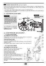
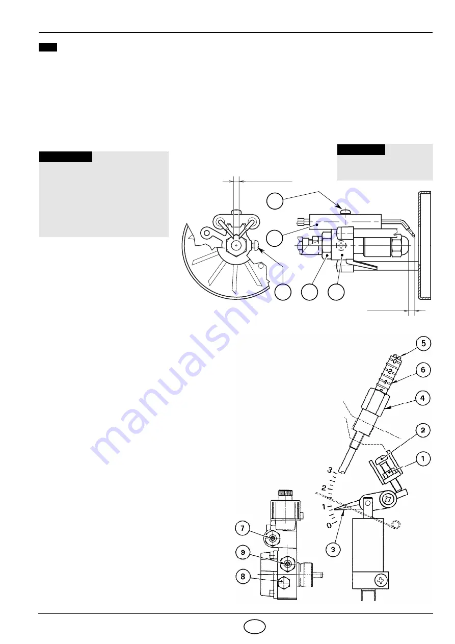
  COMBUSTION HEAD SETTING  (see fig. 12, page 6)

It depends on the output of the burner and is carried out by rotating clockwise or counterclockwise the set-
ting screw (6) until the set-point marked on the regulating rod (7) is level with  the  outside  plane  of  the
nozzle-holder assembly (1).

– In the sketch  the combustion head is set for an output of  2.25 GPH at 15 bar.

The  set-point  2.5  of  the regulating rod is at the same level with the outside plane of the nozzle-holder as-
sembly as shown in the schedule.

4.2

ELECTRODES ADJUSTMENT 

2

Fig. 15

Fig. 14

S7064


Lean the diffuser disc-holder
assembly (1) on the nozzle-
holder (2) and lock it by screw
( 3 ) .   For prospective adjust-
ments loosen screw (4) and
move the electrodes assembly
(5), (see fig. 13).

ATTENTION

To have access to the electrodes
carry out operation as described in
chapter 4.1 (page 6) “RECOM-
MENDED NOZZLES”.

D5341

6 – 7 

mm

4.5 

– 0.5 mm

0

Fig. 13

4

5

1

2

3


MEASURES MUST BE
RESPECTED

WARNING

4.3

PUMP PRESSURE AND AIR OUTPUT

1

st

 STAGE ADJUSTMENT

ADJUSTMENT OF AIR SHUTTER:


Unloosen the nut (1), turn the screw (2) until the indicator (3) reaches the
position desired. Then lock the nut (1), (see fig. 14).

PRESSURE REGULATION:

This is set at 9 bar at the factory.
Should it be necessary to re-set or alter such pressure, this can be done, by
adjusting screw (7).
The  pressure  gauge  must  be  mounted  in  place  of  cap  (8), (see fig. 15).

2

nd

 STAGE ADJUSTMENT

ADJUSTMENT OF AIR SHUTTER:

Unloosen the nut (4), turn the screw (5) until the
indicator (3) reaches the position desired. 
Then lock the nut (4), (see fig. 14).

PRESSURE REGULATION:

This is set at 15 bar at the factory.
Should it be necessary to re-set or alter such  pres-
sure,  this  can  be  done, by adjusting screw (9).
The pressure gauge must be mounted in place of
cap (8), (see fig. 15).

When burner shuts down the air damper automati-
cally closes till a max. chimney depressure of
0,5 mbar.

Summary of Contents for 3739451

Page 1: ... Istruzioni per installazione uso e manutenzione 2902332 4 Bruciatore di gasolio Öl Gebläsebrenner Brûleur fioul Oil burner CODICE CODE MODELLO MODELL MODELE MODEL TIPO TYP TYPE 3739451 RG3D 394 T1 I D F GB Funzionamento bistadio Zweistufiger Betrieb Fonctionnement à 2 allures Two stage operation ...

Page 2: ......

Page 3: ...ne della combustione 6 4 2 Regolazione elettrodi 7 4 3 Pressione pompa e portata aria 7 4 4 Programma di avviamento 8 5 MANUTENZIONE 8 6 ANOMALIE RIMEDI 9 7 NORME GENERALI DI SICUREZZA 10 1 Pompa con variatore di pressione 2 Ritardatore elettronico 3 Apparecchiatura di comando e controllo 4 Pulsante di sblocco con segnalazione di blocco 5 Flangia con schermo isolante 6 Gruppo regolazione serranda ...

Page 4: ...ofase 230V 10 50Hz Motore 2A assorbiti 2730 g min 286 rad s Condensatore 6 3 µF Trasformatore d accensione Secondario 8 kV 16 mA Pompa Pressione 8 15 bar Potenza elettrica assorbita 0 39 kW 228 142 300 213 160 190 12 36 285 345 1 1 99 99 127 4 5 4 5 D5353 ø 123 5 6 7 8 Portata di gasolio kg h 60 Potenza termica kW 1 6 1 2 0 8 0 4 0 Pressione in camera di combustione mbar D5356 9 10 80 2 0 2 4 11 1...

Page 5: ... lo schermo isolante 4 vedi fig 2 Ad installazione avvenuta verificare che il bruciatore sia leggermente inclinato come in fig 5 3 2 ALIMENTAZIONE DEL COMBUSTIBILE Il bruciatore è predisposto per ricevere i tubi di alimentazione del gasolio da entrambi i lati A seconda che l uscita dei tubi avvenga a destra o a sinistra del bruciatore si dovranno invertire sia la piastrina di fissaggio 1 che il pr...

Page 6: ... la valvola di fondo Se invece la tubazione di ritorno arriva sopra il livello del com bustibile la valvola di fondo è indispensabile Questa soluzione è meno sicura della precedente per la possibile mancanza di tenuta della valvola 1 Aspirazione 2 Ritorno 3 Vite di by pass 4 Attacco manometro 5 Regolatore di pressione 2 stadio 6 Attacco vacuometro 7 Regolatore di pressione 1 stadio 8 Pistoncino va...

Page 7: ...ax Termostato di limite Segnalazione di blocco a distanza 230V 0 5A max Elettrodi di accensione Nero L Contaore 2 stadio 230V 0 1A max T h T Valvola olio 2 stadio T8 T7 T6 B5 Spina 4 poli Presa 4 poli Blu Nero Bianco Blu Marrone 2 1 3 2 1 M RITARDATORE ELETTRONICO Termostato Motore 2 stadio M 1 2 1 2 3 M Marrone ESEGUITO IN FABBRICA Termostato di sicurezza NON SCAMBIARE IL NEUTRO CON LA FASE ATTEN...

Page 8: ...MONTARE L UGELLO ESEGUIRE LE SEGUENTI OPERAZIONI Estrarre il gruppo portaugello 1 dopo aver allen tato le viti 2 svitato il dado 3 sfilato i cavetti 4 dall apparecchiatura e la fotoresistenza 5 vedi fi 12 Sfilare i cavetti 4 dagli elettrodi estrarre dal gruppo portaugello 1 il gruppo supporto elica 8 dopo aver allentato la vite 3 fig 13 pag 7 Avvitare l ugello 9 correttamente stringen dolo come mo...

Page 9: ...5 1 2 3 LE MISURE DEVONO ESSERE RISPETTATE ATTENZIONE 4 3 PRESSIONE POMPA E PORTATA ARIA REGOLAZIONE 1 STADIO REGOLAZIONE SERRANDA ARIA Allentare il dado 1 agire sulla vite 2 e portare l indice 3 sulla posi zione desiderata Quindi bloccare il dado 1 vedi fig 14 REGOLAZIONE PRESSIONE Viene tarata in fabbrica a 9 bar Se è necessario ritarare tale pressione o se si preferisce cambiarla basta agire su...

Page 10: ...ione elettrica al bruciatore agendo sull interruttore generale dell impianto LE OPERAZIONI BASILARI DA EFFETTUARE SONO LE SEGUENTI Controllare che non ci siano eventuali occlusioni o ammaccature nei tubi di alimentazione e ritorno del combustibile Effettuare la pulizia del filtro di linea di aspirazione del combustibile e del filtro della pompa Rilevare il corretto consumo di combustibile Cambiare...

Page 11: ... tecnici il cui personale partecipa periodicamente a corsi di istruzione e aggiornamento presso il Centro di Formazione aziendale ANOMALIE POSSIBILE CAUSA RIMEDIO Il bruciatore non par te alla chiusura del termostato di limite Manca l alimentazione elettrica Verificare presenza tensione ai morsetti L1 N della spina 7 poli Verificare lo stato dei fusibili Verificare che il termostato di sicurezza n...

Page 12: ...nato solo all uso per il quale é stato espressamente previsto Ogni altro uso é da considerarsi improprio e quindi pericoloso In particolare può essere applicato a caldaie ad acqua a vapo re ad olio diatermico e su altre utenze espres samente previste dal costruttore il tipo e la pressione del combustibile la tensione e frequenza della corrente elettrica di alimenta zione le portate minime e massim...

Page 13: ...es Verdrahtungsschema 5 4 BETRIEB 6 4 1 Einstellung der Brennerleistung 6 4 2 Elektrodeneinstellung 7 4 3 Pumpendruck und Luftdurchsatz 7 4 4 Betriebsablauf 8 5 WARTUNG 8 6 STÖRUNGEN ABHILFE 9 1 Ölpumpe mit Druck Umschalter 2 Elektronischer Verzögerer 3 Steuergerät 4 Entstörtaste mit Störanzeige 5 Kesselflansch mit Isolierdichtung 6 2 Stufe Luftklappenregulierung 7 Düsenstock 8 Photowiderstand 9 L...

Page 14: ... C Stromversorgung Einphasig 230V 10 50Hz Motor Stromaufnahme 2 A 2730 U min 286 rad s Kondensator 6 3 µF Zündtransformator Sekundärspannung 8 kV 16 mA Pumpe Druck 8 15 bar Leistungsaufnahme 0 39 kW 228 142 300 213 160 190 12 36 285 345 1 1 99 99 127 4 5 4 5 D5353 ø 123 5 6 7 8 Heizöldurchsatz kg h 60 Brennerleistung kW 1 6 1 2 0 8 0 4 0 Druck im Feuerraum mbar D5356 9 10 80 2 0 2 4 11 15 100 120 ...

Page 15: ...mit Isolierdichtung 4 montieren siehe Abb 2 Nach Abschluß der Montagearbeiten überprüfen ob der Brenner leicht geneigt ist wie in Abb 5 3 2 BRENNSTOFFVERSORGUNG Die Ölschläuche werden mit den Winkelanschlüssen an der Ölpumpe montiert wobei die Ölschläuche nach links oder nach rechts aus dem Brenner herausgeführt werden können Es muß jeweils die Halteschelle 1 bzw die Kabelzugentlastung 2 gewechsel...

Page 16: ...kann auf ein Fußventil in der Saugleitung verzichtet werden Endet die Rücklauf Leitung über dem Ölni veau wird auf der Saugseite zwingend ein Fußventil benötigt wobei dieses dann bei Verschmutzung Probleme verursachen kann 8 H meter L meter ø i 8 mm ø i 10 mm 0 5 1 1 5 2 10 20 40 60 20 40 80 100 Es muß sichergestellt werden daß die Ölrücklauf Leitung ohne Verengung und Verstopfung frei in den Tank...

Page 17: ... L T h T 2 Stufe Ölventil T8 T7 T6 B5 Blau Schwarz Weiß Blau Braun 2 1 3 2 1 M ELEKTRONISCHER VERZÖGERER 2 Stufe Thermostat Motor M 1 2 1 2 3 M Braun WERKSSEITIGE EINSTELLUNG D6123 STEUERGERÄT 550SMD 1 Stufe Betriebs 230V 0 1A max stundenzähler 2 Stufe Betriebsstundenzähler 230V 0 1A max 4 poliger Stecker 4 polige Steckdose 1 Stufe Ölventil ANMERKUNGEN Leiterdurchmesser 1 mm2 Die vom Installateur ...

Page 18: ...tock 1 herausnehmen nachdem vorher die Schrauben 2 gelockert die Mutter 3 gelöst die Zündkabel 4 vom Steuergerät und der Photowiderstand 5 abgenommen wur den siehe Abb 12 Die Zündkabel 4 von den Elektroden abneh men den Stauscheibenhalter 8 vom Düsenstock 1 herausnehmen nachdem die Schraube 3 Abb 13 Seite 7 gelockert wurde Die Düse 9 richtig anschrauben wie in Abbildung 12 abgebildet ACHTUNG Bei d...

Page 19: ... im Kapitel 4 1 unter dem Stichpunkt EMPFOHLENE DÜSEN S 6 beschriebene Anlei tung befolgen DIE ABSTÄNDE MÜSSEN EINGEHALTEN WERDEN WICHTIGER HINWEIS 4 3 PUMPENDRUCK UND LUFTDURCHSATZ EINSTELLUNG 1 STUFE LUFTKLAPPENEINSTELLUNG Die Kontermutter 1 lösen und durch Drehen der Schraube 2 den Zeiger 3 auf die gewünschte Stellung einstellen Dann die Kontermutter 1 wieder festdrehen siehe Abb 14 DRUCKEINSTE...

Page 20: ...ichergestellt daß bestmögliche Energie Verbrauchswerte erreicht werden was mit einer Schadstoff Re duzierung gleichzusetzten ist Vor jeder Wartungsarbeit den Brenner stromios schalten WICHTIGSTE WARTUNGSARBEITEN Überprüfen ob die Ölversorgungsleitung und die Rücklaufleitung weder verstopft noch geknickt sind Filter in der Versorgungsleitung und an der Pumpe reinigen Korrekten Brennstoffverbrauch ü...

Page 21: ...em Personal verursacht werden ist ausgeschlossen STÖRUNGEN MÖGLICHE URSACHE ABHILFE Der Brenner fährt bei der Auslösung des Begrenzungs thermostates nicht an Keine Stromzufuhr Spannung zwischen den Klemmen L1 N des 7 poligen Steckers prüfen Sicherungen überprüfen Überprüfen ob der Sicherheitstempe raturbegrenzer von Hand entriegelt werden muss Der Photowiderstand meldet Fremdlicht Lichtquelle bese...

Page 22: ...ONCTIONNEMENT 6 4 1 Réglage de la combustion 6 4 2 Réglage des électrodes 7 4 3 Pression pompe et débit air 7 4 4 Programme de mise en marche 8 5 ENTRETIEN 8 6 PANNES REMEDES 9 1 Pompe avec variateur de pression 2 Retardateur électronique 3 Boîte de commande et de contrôle 4 Bouton de réarmement avec signalisation de sécurité 5 Bride avec joint isolant 6 Réglage du volet d air 2ème allure 7 Porte ...

Page 23: ...trique Monophasée 230V 10 50Hz Moteur 2A absorbés 2730 t min 286 rad s Condensateur 6 3 µF Transformateur d allumage Secondaire 8 kV 16 mA Pompe Pression 8 15 bar Puissance électrique absorbée 0 39 kW 228 142 300 213 160 190 12 36 285 345 1 1 99 99 127 4 5 4 5 D5353 ø 123 5 6 7 8 Débit fioul kg h 60 Puissance thermique kW 1 6 1 2 0 8 0 4 0 Pression dans a chambre de combustion mbar D5356 9 10 80 2...

Page 24: ...sant le joint isolant 4 voir fig 2 Lorsque le montage est terminé vérifier que le brûleur soit légèrement incliné comme en figure 5 3 2 ALIMENTATION DU COMBUSTIBLE Le brûleur est prééquipé pour recevoir les tubes d alimentation du fioul des deux cotés Selon que la sortie des flexibles est à droite ou à gauche il peut y avoir lieu de changer l emplacement de la plaque de fixation 1 avec la traverse...

Page 25: ...a pas besoin de clapet de pied Dans le cas contraire le clapet de pied est indispensable Cette deuxième solution est moins sûre que la précédente en raison du manque d étanchéité éventuel de ce clapet H mètres L mètres ø i 8 mm ø i 10 mm 0 5 1 1 5 2 10 20 40 60 20 40 80 100 Avant de mettre en fonction le brûleur il faut s assurer que le tube de retour du combustible ne soit pas obstrué Une contre ...

Page 26: ...ur des générateurs à air chaud enlever le pont B fig 11 de la boîte de contrôle Fig 11 E9070 B A Led vert Ventilateur Led jaune Réchauffeur Led rouge Signalisation de mise en sé curité due à non extinction 1ère allure D6123 Compteur horaire 1ère allure 230V 0 1A max Compteur horaire 2ème allure 230V 0 1A max 550SMD BOITE DE CONTROLE NOTES Section conducteurs 1 mm2 Les branchements électriques exéc...

Page 27: ...ligne porte gicleur 1 après avoir des serré les vis 2 dévissé l écrou 3 débranché les câbles 4 de la boîte de contrôle et la cellule photorésistance 5 voir fig 12 Débrancher les câbles 4 des électrodes enle ver de la ligne porte gicleur 1 le support de l accroche flamme 8 après avoir desserré la vis 3 fig 13 page 7 Visser correctement le gicleur 9 en le ser rant comme indiqué en figure 12 ATTENTIO...

Page 28: ... LES DISTANCES DOIVENT ETRE RESPECTEE ATTENTION Fig 15 Fig 14 S7064 REGLAGE 1ère ALLURE REGLAGE VOLET D AIR Desserrer l écrou 1 tourner la vis 2 jusqu à ce que l index 3 atteigne la position désirée et après bloquer l écrou 1 voir fig 14 REGLAGE DE LA PRESSION FIOUL Le réglage à 9 bar a lieu à l usine Si la pression doit être modifiée il suffit de tourner la vis 7 Le manomètre pour le contrôle de ...

Page 29: ...r l alimentation électrique en agissant sur l interrupteur général LES OPERATIONS ESSENTIELLES A EFFECTUER SONT Contrôler qu il n y a pas d obturation ou d altération des tuyauteries d alimentation et de retour du com bustible Effectuer le nettoyage du filtre de la ligne d aspiration du combustible et le filtre de la pompe Vérifier si la consommation est correcte Changer le gicleur Nettoyer la têt...

Page 30: ... Absence d alimentation électrique Vérifier la tension au bornier L1 N de la fiche à 7 pôles Vérifier les fusibles Vérifier que le thermostat de sécurité ne soit pas intervenu La cellule photorésistance est éclairée par une source lumineuse externe Supprimer cette source lumineuse Thermostat hors d usage Procéder à leur changement Les branchements de la boîte de contrôle ne sont pas corrects Contr...

Page 31: ...4 1 Combustion adjustment 6 4 2 Electrodes adjustment 7 4 3 Pump pressure and air output 7 4 4 Burner start up cycle 8 5 MAINTENANCE 8 6 FAULTS SOLUTIONS 9 1 Pump with pressure reducer 2 Electronic start delaying device 3 Control box 4 Reset button with lock out lamp 5 Flange with insulating gasket 6 2nd stage air damper adjustment assembly 7 Nozzle holder assembly 8 Photoresistance 9 Hydraulic ja...

Page 32: ...ly Single phase 230V 10 50Hz Motor Run current 2 A 2730 rpm 286 rad s Capacitor 6 3 µF Ignition transformer Secondary 8 kV 16 mA Pump Pressure 8 15 bar Absorbed electrical power 0 39 kW 228 142 300 213 160 190 12 36 285 345 1 1 99 99 127 4 5 4 5 D5353 ø 123 5 6 7 8 Light oil output kg h 60 Thermal power kW 1 6 1 2 0 8 0 4 0 Pressure in combustion chamber mbar D5356 9 10 80 2 0 2 4 11 15 100 120 12...

Page 33: ... 2 interposing the insulating gasket 4 see fig 2 After installation ensure that burner is lightly inclined as in fig 5 3 2 FUEL SUPPLY The burner is designed to allow entry of the oil supply pipes on either side Depending on the oil supply pipes position to the right or to the left hand side of the burner the fixing plate 1 and cable clamp 2 should be reversed see fig 6 Fig 5 D5012 Fig 4 D5025 Fig...

Page 34: ...ot required Should however the return line arrive over the fuel level a non return valve is required This solution however is less safe than previous one due to the possibility of leakage of the valve 8 H meters L meters ø i 8 mm ø i 10 mm 0 5 1 1 5 2 10 20 40 60 20 40 80 100 Before starting the burner make sure that the return pipe line is not clogged An excessive back pressure would cause the da...

Page 35: ... A with a torque wrench setting of 1 1 2 Nm For burners installed on air generators remove the bridge B fig 11 from the control box Fig 11 E9070 B A Green led Fan Yellow led Heater Red led Lock out signalling due to failure to shut down 1st stage oil valve D6123 Limit thermostat Remote lock out signal 230V 0 5A max Safety thermostat 1st stage hour counter 230V 0 1A max 2nd stage hour counter 230V ...

Page 36: ...ve nozzle holder assembly 1 after loos ing screws 2 and nut 3 remove the small cables 4 from the control box and the pho toresistance 5 see fig 12 Withdraw the small cables 4 from the elec trodes remove the diffuser disc holder assembly 8 from the nozzle holder assembly 1 after loosing screw 3 fig 13 page 7 Screw the nozzle 9 correctly and tighten it as shown in figure 12 ATTENTION During the reas...

Page 37: ...hapter 4 1 page 6 RECOM MENDED NOZZLES D5341 6 7 mm 4 5 0 5 mm 0 Fig 13 4 5 1 2 3 MEASURES MUST BE RESPECTED WARNING 4 3 PUMP PRESSURE AND AIR OUTPUT 1st STAGE ADJUSTMENT ADJUSTMENT OF AIR SHUTTER Unloosen the nut 1 turn the screw 2 until the indicator 3 reaches the position desired Then lock the nut 1 see fig 14 PRESSURE REGULATION This is set at 9 bar at the factory Should it be necessary to re ...

Page 38: ...ectrical supply to the bur ner acting on the main switch of the system THE BASIC CHECKS ARE Check that there are not obstructions or dents in the supply or return oil pipes Clean the filter in the oil suction line and in the pump Check for correct fuel consumption Replace the nozzle Clean the combustion head in the fuel exit area on the diffuser disc Leave the burner working without interruptions ...

Page 39: ...S POSSIBLE CAUSES SOLUTION The burner doesn t start when the limit thermostat closes Lack of electrical supply Check presence of voltage in the L1 N clamps of the 7 pin plug Check the conditions of the fuses Check that safety thermostat is not lock out The photoresistance sees strange light Eliminate the light Thermostats are faulty Replace them The connections in the control box are wrongly inser...

Page 40: ......

Reviews: