background image


2604


3


GB


HYDRAULIC SYSTEM


Warning:


before starting the burner make sure that the return pipe-line is not clogged: any obstruc-
tion would cause the pump seals to break.

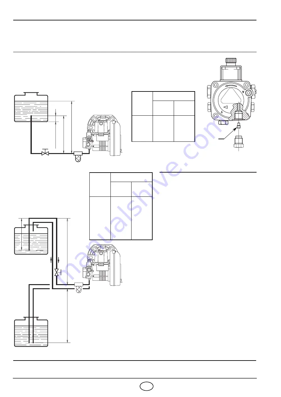
The pump vacuum should not exceed a
maximum of 0.4 bar (30 cm Hg).
Beyond this limit gas is released from
the oil.

Oil lines must be completely air-
tight.

The return line should terminate in
the oil tank at the same level as the
suction line
; in this case a non-return
valve is not required.

When the return line arrives over the
fuel level, a non-return valve must be
used.

This solution however is less safe than
previous one, due to the possibility of
leakage of the valve.

PRIMING THE  PUMP

Start the burner and wait for the priming.
Should lock-out occur prior to the arrival
of the fuel, await at least 20 seconds
before repeating the operation.

A  filter must be installed on the suction fuel line.

H

meters

L meters

I. D.

8 mm

I.D.

10 mm

0.5

1

1.5

2

10
20
40
60

20
40
80

100

WARNING

The pump is supplied for use with a two pipe system. 
For use on a one pipe system, it is necessary to remove the by-pass
screw (A),

 (see figure).

A

H

meters

L meters

I. D.

8 mm

I.D.

10 mm

0

0.5

1

1.5

2
3

3.5

35
30
25
20
15

8
6

100
100
100

90
70
30
20

H

max.

 4 m

H

H

max.

 4 m

min.

 0.1 m

D5616

D5617

D5199

=

Difference of level.

L

= Max. 

length of the 

suction line.

I.D. =

Internal diameter of the

oil pipes.

PRIMING THE  PUMP

Loosen the plug of the vacuum gauge (5, fig. 1,
page 1) and wait until the fuel flows out.

Summary of Contents for 3742693

Page 1: ...2902604 1 Installation use and maintenance instructions O Oil burner CODE MODEL TYPE 3742693 G3X 450 M1 GB GR One stage operation...

Page 2: ...er Secondary 8 kV 16 mA Pump Pressure 7 15 bar Absorbed electrical power 0 115 kW 1 Return line 2 Suction line 3 Gauge connection 4 Pump pressure regulator 5 Vacuum gauge connection 6 Screws fixing ai...

Page 3: ...115 79 194 130 4 5 11 164 D6219 180 75 72 150 4 5 89 109 It is necessary that the insulating gasket 9 fig 1 is placed between the boiler door and the burner flange This insulating gasket has six holes...

Page 4: ...leakage of the valve PRIMING THE PUMP Start the burner and wait for the priming Should lock out occur prior to the arrival of the fuel await at least 20 seconds before repeating the operation A filter...

Page 5: ...h the ignition trans former on a plug in support TESTING Check the shut down of the burner by opening the thermostats ATTENTION Do not connect burner s grounding to failure indicator terminal This may...

Page 6: ...in case of flame detachment during ignitions at low tem peratures PUMP PRESSURE 12 bar the pump leaves the factory set at this value 14 bar improves flame retention it is therefore suitable for igniti...

Page 7: ...not advisable for ignitions at low temperatures In any case do not bring the combustion head setting more than one point away from that indicated in the schedule One set point corresponds to 3 turns o...

Page 8: ...below 8 C increase the pressure to 14 bar 4 COMBUSTION HEAD SETTING Regulate the combustion head one set point further ahead than indicated in the instructions Example the instructions require to set...

Page 9: ...GR E HNIKA CE EMC 89 336 E 92 42 E 19 35 kW 1 6 3 kg h diesel 6 mm2 s 20 C 230 V 10 50 Hz 0 7A 2 850 rpm 298 rad s 4 F 8 kV 16 mA 7 15 bar 0 115 kW 1 2 3 4 5 6 7 8 9 10 2 1 4 1 5 D6218 1 2 3 4 8 6 6 7...

Page 10: ...2604 2 GR 0 8 0 0 2 0 4 mbar 1 5 2 2 5 3 kg h 20 25 30 35 kW D5223 0 6 115 79 194 130 4 5 11 164 D6219 180 75 72 150 4 5 89 109 2 D5242 D5891 2 S7386...

Page 11: ...bar 20 sec L i 8 mm i 10 mm 0 5 1 1 5 2 10 20 40 60 20 40 80 100 by pass A L i 8 mm i 10 mm 0 0 5 1 1 5 2 3 3 5 35 30 25 20 15 8 6 100 100 100 90 70 30 20 H max 4 m H H max 4 m min 0 1 m D5616 D5617 D...

Page 12: ...2604 4 GR 50V 6A max N L M 1 mm2 530SE 230V 50Hz N L 230V 0 5A max 1 2 3 4 5 6 7 8 9 530SE T T 1 N 2 L D5228 M A 1 2 L...

Page 13: ...20 C Monarch R NS Delavan W A E Steinen H Q Danfoss 60 80 12 bar 14 bar GPH bar kg h 4 0 40 80 12 1 6 0 2 7 0 50 60 80 12 2 0 1 3 3 0 60 60 80 12 2 4 2 4 0 65 60 80 12 2 6 3 5 5 0 75 60 12 3 0 4 7 1...

Page 14: ...2604 6 GR 1 6 mm 2 o CO2 CO2 1 3 1 2 3 6 D5497 B A D5780 B 4 2 2 5 mm 4 0 3 mm D5230 C C...

Page 15: ...2604 7 GR 8 C F 1 2 M Delavan A E Steinen H Danfoss H 3 12 bar 8 C 14 bar 4 2 3 5 BACCARACH 1 12s D5229 12s 5s 2 2 5 mm 4 0 3 mm D5794 C...

Page 16: ......

Reviews: