background image

8

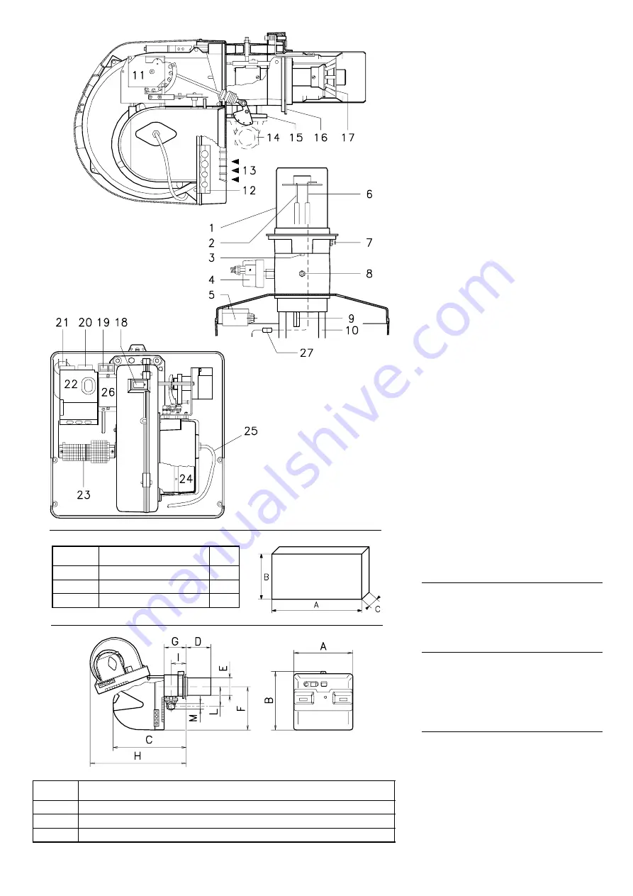
DESCRIZIONE BRUCIATORE (A)

1 Testa di combustione
2 Elettrodo d’accensione
3 Vite per regolazione testa di combustione
4 Pressostato gas di massima
5 Pressostato aria (tipo differenziale)
6 Sonda per il controllo presenza fiamma 
7 Presa di pressione aria 
8 Presa di pressione gas e vite fissa testa
9 Vite per il fissaggio ventilatore al manicotto 
10 Guide per apertura bruciatore ed ispezione

alla testa di combustione 

11 Servomotore, comanda la farfalla del gas e,

tramite una camma a profilo variabile, la ser-
randa dell’aria.
Durante la sosta del bruciatore la serranda
dell’aria è completamente chiusa per ridurre
al minimo le dispersioni termiche della cal-
daia dovute al tiraggio del camino che
richiama l’aria dalla bocca di aspirazione del
ventilatore.

12 Piastrina predisposta per ottenere 4 fori, utili

al passaggio dei cavi elettrici

13 Ingresso aria nel ventilatore
14 Condotto arrivo gas
15 Valvola farfalla gas
16 Flangia per il fissaggio alla caldaia
17 Disco di stabilità fiamma
18 Visore fiamma
19 Un interruttore per:

funzionamento automatico-manuale-spento
Un pulsante per:
aumento - diminuzione potenza 

20 Contattore motore e relè termico con pul-

sante di sblocco (RS 38-50/M)

21 Condensatore motore (RS 28/M)
22 Apparecchiatura elettrica con avvisatore

luminoso di blocco e pulsante di sblocco

23 Morsettiera per il collegamento elettrico 
24 Serranda aria 
25 Tubetto che collega l’aspirazione del ventila-

tore al pressostato aria

26 Staffa per l’applicazione del regolatore di

potenza RWF40

27 Spina-presa sul cavo della sonda di ionizza-

zione 

Vi sono due possibilità di blocco del bruciatore:

• BLOCCO APPARECCHIATURA:


l’accensione del pulsante dell’apparecchiatura
22)(A) avverte che il bruciatore è in blocco.
Per sbloccare premere il pulsante.

• BLOCCO MOTORE

 (RS 38-50/M):

alimentazione elettrica a due fasi, per sbloc-
care premere il pulsante del relè termico
20)(A).

IMBALLO - PESO (B)

 - misure indicative

• I bruciatori vengono spediti in imballi di car-

tone con dimensioni di ingombro secondo
tab. (B).

• Il peso del bruciatore completo di imballo è

indicato nella tab. (B).

INGOMBRO (C)

 - misure indicative

L'ingombro del bruciatore è riportato in fig.(C).
Tener presente che per ispezionare la testa di
combustione il bruciatore deve essere arretrato
e ruotato verso l’alto.
L'ingombro del bruciatore aperto, senza cofano,
è indicato dalla quota H.

CORREDO

1 - Flangia per rampa gas
1 - Guarnizione per flangia
4 - Viti per fissare la flangia M 8 x 25
1 - Schermo termico
4 - Viti per fissare la flangia del bruciatore alla

caldaia: M 8 x 25

5 - Passacavi per collegamento elettrico 

(RS 28/M)

6 - Passacavi per collegamento elettrico 

(RS 38-50/M)

1 - Istruzione
1 - Catalogo ricambi

(B)


mm

(1)

B

C

kg

RS 28/M

872-1007

550

540

38

RS 38/M

872-1007

550

540

40

RS 50/M

872-1007

550

540

41

(1) Boccaglio: corto-lungo / Flammenrohr: kurz-lang / Blast tube: short-long / Buse: courte-longue

mm

A

B

C

(1)

E

F

G

H

I

L

M

RS 28/M

476

474

580

216-351

140

352

164

810

108

168

1”

1/2

RS 38/M

476

474

580

216-351

140

352

164

810

108

168

1”

1/2

RS 50/M

476

474

580

216-351

152

352

164

810

108

168

1”

1/2

(C)

(A)

D776

D777

D778

D88

D495

Summary of Contents for 3781012

Page 1: ...as burners Br leurs gaz air souffl 2915608 4 02 2008 CODICE CODE MODELLO MODELL MODEL MODELE TIPO TYP TYPE 3781012 RS 28 M 824 T1 3781013 RS 28 M 824 T1 3781412 RS 38 M 825 T1 3781413 RS 38 M 825 T1 3...

Page 2: ......

Page 3: ...ieb sanleitung der Heizkessels ausgef hrt werden einschlie lich Kontrolle der Konzentration von CO und CO2 in den Abgasen ihrer Temperatur und der mittlenen Kesseltemperatur D CONTENTS TECHNICAL DATA...

Page 4: ...1 6 6 9 7 7 2 10 6 FUNZIONAMENTO Intermittente min 1 arresto in 24 ore Questi bruciatori sono adatti anche al funzionamento continuo se ven gono equippaggiati con l apparecchiatura Landis LGK 16 333...

Page 5: ...haltung in 24 Std Wenn dieser Brenner mit dem Gasfeuerungsautomaten Landis Gyr LGK 16 333 A27 ausgestattet ist ist er auch f r den Dauerbetrieb gee ignet Die elektrische Verdrahtung des Brenners bleib...

Page 6: ...7 7 2 10 6 OPERATION On Off 1 stop min each 24 hours This burner is also fitted for the continuos operation if it is equipped with the control box LANDIS type LGK 16 333 A27 interchangeable with the b...

Page 7: ...max 2 mbar 7 5 11 1 6 6 9 7 7 2 10 6 FONCTIONNEMENT Intermittent 1 arr t min en 24 heures Ce br leurs est appropri s aussi pour le service permanent s il est quip s avec le bo tier LANDIS type LGK 16...

Page 8: ...ressostato aria 26 Staffa per l applicazione del regolatore di potenza RWF40 27 Spina presa sul cavo della sonda di ionizza zione Vi sono due possibilit di blocco del bruciatore BLOCCO APPARECCHIATURA...

Page 9: ...trical connection 24 Air gate valve 25 Pipe connection the fan air inlet to the air pressure switch 26 Bracket for mounting the power regulator RWF40 27 Plug socket on ionisation proble cable Two type...

Page 10: ...676 Riportiamo in B diametro e lunghezza della camera di combustione di prova Esempio Potenza 350 Mcal h diametro 50 cm lunghezza 1 5 m CALDAIE COMMERCIALI L abbinamento bruciatore caldaia non pone pr...

Page 11: ...e firing rates were set in relation to special test boilers according to EN 676 regulations Figure B indicates the diameter and length of the test combustion chamber Example Output 350 Mcal h diameter...

Page 12: ...alla quale si desidera funzioni il bruciatore trovare nella tabella relativa al bruciatore con siderato il valore di potenza pi vicino al val ore desiderato Leggere sulla destra colonna 1A o B la pre...

Page 13: ...er in question Read off the corresponding output on the left Example RS 28 M Maximum output operation Natural gas G 20 PCI 10 kWh Nm3 Gas ring 2 B p 16 adjusted as indicated in diagram C p 16 Gas pres...

Page 14: ...ati come in C Separare quindi la testa di combustione dal resto del bruciatore fig B togliere la vite 14 ed estrarre il cofano 15 sganciare lo snodo 4 dal settore graduato 5 togliere le viti 2 dalle d...

Page 15: ...hrough the blast tube opening to make sure that the flame sensor probe and the ignition electrode are correctly set in position as shown in C Now detach the combustion head from the burner fig B remov...

Page 16: ...iva di pulsazioni B La potenza MIN del bruciatore com presa nei valori della tabella D Regolazione aria Vale quanto detto per il caso precedente seg uire il diagramma C Regolazione gas La ghiera 2 B v...

Page 17: ...ressure indi cated on page 12 and if the ring 2 B is not fully open it can be opened wider by 1 or 2 notches Continuing with the previous example page 12 indicates that for burner RS 38 M with output...

Page 18: ...a monte del filtro L Rampa gas fornita a parte con il codice indicato in tab C L1 A cura dell installatore LEGENDA TABELLA C C T Dispositivo controllo tenuta valvole gas 8 9 Rampa priva del dispositiv...

Page 19: ...rd issue burner gasket with flange 11 Gas adjustment butterfly valve 12 Burner 13 Gas valve 8 9 leak detection control device In accordance with EN 676 Standards gas valve leak detection control devic...

Page 20: ...7 C del bruciatore vanno fatti passare dai passacavi for niti a corredo da inserire nei fori della piastrina di destra o di sinistra dopo aver svitato le viti 8 aperto la piastrina nelle parti 9 e 10...

Page 21: ...in rubber sheath use at least H05 RR F All the wires to connect to the burner terminal strip 7 C must enter through the supplied fair leads which must be fitted into the relevant holes in the left ha...

Page 22: ...di funzionamento TL Telecomando di limite ferma il bruciatore quando la temperatura o la pressione in caldaia raggiunge il val ore prestabilito TS Telecomando di sicurezza interviene in caso di TL gu...

Page 23: ...te lock out signal S1 Remote lock out signal of leak detection control device TR High low mode load remote control system controls operating stages 1 and 2 TL Load limit remote control system shuts do...

Page 24: ...20 A p 8 Serve ad evitare la bruciatura del motore per un forte aumento dell assorbimento dovuto alla mancanza di una fase Se il motore alimentato a stella 400 V il cur sore va posizionato sul MIN Se...

Page 25: ...als AL AL1 to replace the remote control TL or to control an external device LAYOUT F Calibration of thermal cut out 20 A p 8 This is required to avoid motor burn out in the event of a significant inc...

Page 26: ...amma I 90 Limita la rotazione verso il massimo Con il bru ciatore funzionante alla potenza MAX la farfalla del gas deve risultare tutta aperta 90 Camma I I 0 Limita la rotazione verso il minimo A bruc...

Page 27: ...ngle of rotation of the servomoteur is equal to the angle on the graduated sector con trolling the gas butterfly valve The servomotor rotates through 90 degrees in 24 seconds Do not alter the factory...

Page 28: ...ccensione deve essere uguale o inferiore a 300 kW con ts 2 s 200 kW con ts 3 s Per misurare la potenza all accensione scollegare la spina presa 27 A p 8 sul cavo della sonda di ionizzazione il bruciat...

Page 29: ...able the burner will fire and then go into lock out after the safety time has elapsed Perform 10 firings with consecutive lock outs On the meter read the quantity of gas burned This quantity must be e...

Page 30: ...ella che deve portare la serranda dell aria alla totale chiusura 4 POTENZE INTERMEDIE Regolazione del gas Non occorre alcuna regolazione Regolazione dell aria Premere un poco il pulsante 2 A p 28 aume...

Page 31: ...la came I I I et enfin reporter le servomoteur en position de puis sance MIN avec le bouton diminution de la puissance Pour le r glage ventuel de la came I I I retirer le couvercle 1 enclench par pres...

Page 32: ...A B Eseguire la regolazione del pressostato gas di massima dopo aver effettuato tutte le altre regolazioni del bruciatore con il pressostato gas di massima regolato a fine scala B Con il bruciatore fu...

Page 33: ...H B Adjust the maximum gas pressure switch after having performed all other burner adjustments with the maximum gas pressure switch set to the end of the scale B With the burner operating at MAX outpu...

Page 34: ...rretta posizione dei pressostati aria e gas di massima Se la temperatura o la pressione bassa per cui il telecomando TR chiuso il bruciatore aumenta progressivamente la potenza fino al valore MAX trat...

Page 35: ...ntr ler la pr sence de la flamme et la bonne position des pressostats air et gaz maximum Si la temp rature ou la pression sont basses et que par cons quent la t l commande TR est ferm e le br leur aug...

Page 36: ...ntate nei cinematismi che comandano la serranda aria e la farfalla del gas Cos pure bloccate devono essere le viti che fissano i cavi nella morsettiera del bruciatore Pulire esternamente il bruciatore...

Page 37: ...s wear or loose screws in the mechanisms controlling the air gate valve and the gas butterfly valve Also make sure that the screws securing the electrical leads in the burner connections are fully tig...

Page 38: ...tti 10 8 apparecchiatura Superata la preventilazione ed il tempo di sicurezza il bruciatore va in blocco senza apparizione di fiamma 23 L elettrovalvola VR fa passare poco gas Aumentarlo 24 L elettrov...

Page 39: ...abschaltung des Brenners nach der Vorbel ftung und der Sicherheitszeit ohne Flammenbildung 23 Ungen gender Gasflu durch das Magnetventil VR Steigern 24 Magnetventil VR bzw VS ffnet nicht Spule oder Gl...

Page 40: ...servomotor control box terminals 10 8 After pre purge and safety time the burner goes to lock out and the flame does not appear 23 The solenoid VR allows little gas through Increase 24 Solenoid valves...

Page 41: ...Apr s la pr ventilation et le temps de s curit le br leur se bloque sans apparition de flamme 23 Electrovanne VR fait passer peu de gaz Augmenter 24 L lectrovanne VR ou VS ne s ouvre pas Remplacer bo...

Page 42: ......

Page 43: ......

Page 44: ...RIELLO S p A I 37045 Legnago VR Tel 39 0442 630111 http www rielloburners com Con riserva di modifiche nderungen vorbehalten Subject to modifications Sous r serve de modifications...

Reviews: