2814
5
GB
3.3
GAS FEEDING LINE
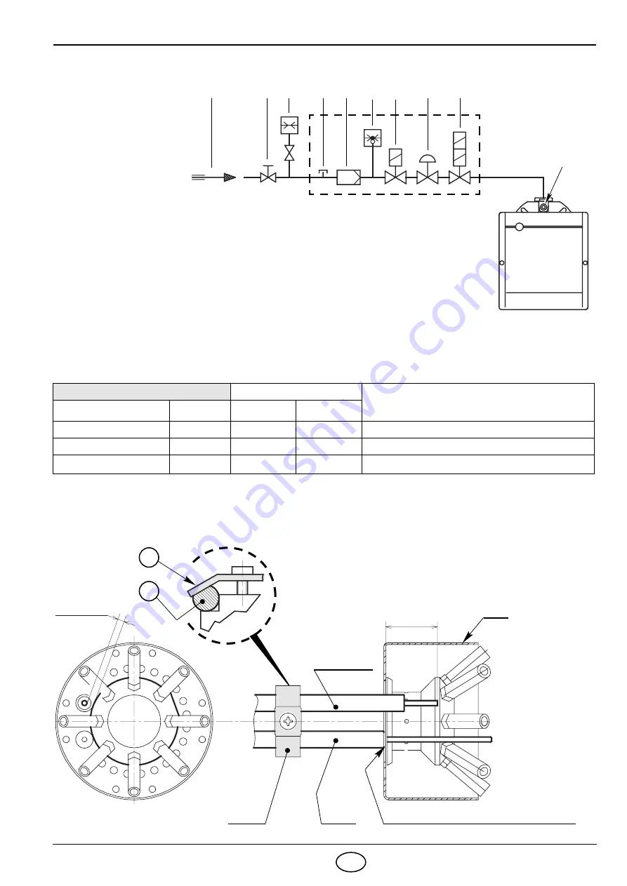
GAS TRAIN ACCORDING TO EN 676
The gas train is supplied separately, for its adjustment see the enclosed instructions.
3.4
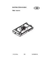
PROBE - ELECTRODE POSITIONING,
(see fig. 7)
GAS TRAIN
CONNECTIONS
USE
TYPE
CODE
INLET
OUTLET
MB-ZRDLE 410 B01
3970542
Rp 1” 1/4
Flange 3
Natural gas
≤
200kW and LPG 160
–
345 kW
MB-ZRDLE 412 B01
3970543
Rp 1” 1/4
Flange 3
Natural gas
≤
300 kW
MB-ZRDLE 415 B01
3970582
Rp 1” 1/2
Flange 3
Natural gas
≥
300 kW
M2
Fig. 6
D5208
1
2
3
M1
5
6
7
4
8
1
– Gas supply pipe
2
– Manual cock
(charged to the installer)
3
– Gas pressure gauge
(charged to the installer)
4 – Filter
5
– Gas pressure switch
6 – Safety
valve
7 – Pressure
governor
8 – 1st and 2nd adjusting valve
M1 – Gas-supply pressure test point
M2 – Pressure coupling test point
ELECTRODE
CUP
Lean the probe insulator against the cup
D4020
31 ±
0.3
PROBE
PLATE
3.5 ±
0.3
Fig. 7
ATTENTION
Verify that the plate (1) is always inserted in the
flattening of the electrode (2).
2
1


