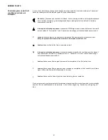
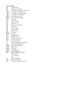
background image

12

Adjusting air delivery
Progressively adjust the end profile of cam 4)(A) by turn-
ing the cam adjustment screws as they appear through
the access opening 6)(A).
- Turn the screws clockwise to increase air delivery.
- Turn the screws counter-clockwise to reduce air deliv-

ery.

3 - MINIMUM OUTPUT

Minimum output must be selected within the firing rate
range shown on page 5.
Press switch 2)(A)p.11 “output reduction” until the servo-
motor has closed the air damper and the gas butterfly
valve to 15° (factory set adjustment).

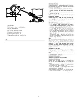
Adjusting gas delivery
Measure the delivery of gas from the gas meter.
- If this value is to be reduced, decrease the angle of

orange cam (B) slightly by proceeding a little at a time
until the angle is changed from 15° to 13° or 11°....

- If it has to be increased press the switch “output

increase” 2)(A)p.11 (i.e. open the gas butterfly valve
by 10-15°), increase the orange cam angle (B) with
small successive movements, i.e. take it from angle
15° to 17° - 19°....
Then press the switch “output decrease” until the ser-
vomotor is taken to the minimum opening position and
measure the gas delivery.

Note

The servomotor follows the adjustment of cam only
when the cam angle is reduced. If it is necessary to
increase the cam angle, first increase the servomotor
angle with the switch “output increase”, then increase
the orange cam angle, and at the end bring the servo-
motor back to the MIN output position with the switch
”output decrease”.

Adjustment of air delivery
Progressively adjust the starting profile of cam 4)(A) by
turning the screws working throught the access hole
6)(A).

4 - INTERMEDIATE OUTPUTS

Adjustment of gas delivery
No adjustment of gas delivery is required.

Adjustment of air delivery
With the switch 1)(A) page 11 move in intermediate out-
puts and set the variable profile cam 4) by turning the
screws 5). 
- If the burner operation is low-high it is sufficient to set

only minimum and maximum firing rates

- If the burner operation is modulating, all the points of

modulation should be adjusted.

When the adjustment is complete, release the servomo-
tor and manually check there is no binding of the cam.

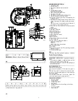
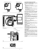
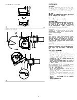
(A)

1 Servomotor
2 Lever, push to engage, push to release

3 Adjustable profile cam
4 Cam profile adjustment screws
5 Opening for access to screws 5
6 Index for graduated sector 8
7 Graduated sector for gas butterfly valve

D2267

Summary of Contents for RS 45/M LN

Page 1: ...Installation use and maintenance instructions Gas Burners RS 45 M LN Low High Low or Modulating Operation C6505071 2915847 2...

Page 2: ...d layout 16 Burner firing rates according to air density 19 Start up report 23 N B Figures mentioned in the text are identified as follows 1 A part 1 of figure A same page as text 1 A p 4 part 1 of fi...

Page 3: ...ANDARDS see page 9 MODEL RS 45 M LN Output 1 MAX MBtu hr 717 2037 1969 _ 210 597 577 _ kW MIN MBtu hr kW 341 100 Fuel Natural gas Max delivery SCFH 2037 Pressure at maximum delivery 2 natural gas WC 5...

Page 4: ...or 24 Burner terminal strip 25 Air damper 26 Bracket for mounting the PID modulating controller RWF40 optional 27 Pilot burner attachment Note If the flame relay 22 A pushbutton lights up it indicates...

Page 5: ...ratures and or altitudes MINIMUM FURNACE DIMENSIONS B The firing rates were set in relation to certified test boil ers Figure B indicates the diameter and length of the test combustion chamber Example...

Page 6: ...Find the nearest pressure value to your result in col umn 1 of the table A Read off the corresponding output on the left Example RS 45 M LN Maximum output operation Natural gas Gas ring 2 B p 8 adjust...

Page 7: ...from the graduated sector 5 Remove the screws 2 from the slide bars 3 Remove screw 1 and pull the burner back on slide bars 3 by about 4 Disconnect the wires from the probe and the electrode and then...

Page 8: ...until the notch identified is aligned with screw 4 Tighten the screws 1 and 4 fully down Example Burner output 1515 MBtu hr If we consult diagram C we find that for this output the adjustments are ou...

Page 9: ...he pilot gas train must be connected to the gas attachment 5 A and can enter the burner from the right or left side GAS TRAIN B It must be type approved according to required local standards and is su...

Page 10: ...he cams simply check that they are set as indicated below Red cam 90 Limits rotation toward maximum position When the burner is at max output the gas butterfly valve must be fully open 90 Blue cam 0 L...

Page 11: ...wn on page 5 In the above instructions we left the burner running in MIN output operation Now press switch 2 A increase output and keep it pressed until the servomotor has opened the air damper and th...

Page 12: ...asure the gas delivery Note The servomotor follows the adjustment of cam only when the cam angle is reduced If it is necessary to increase the cam angle first increase the servomotor angle with the sw...

Page 13: ...etween the air pres sure switch and the suction inlet of the fan In this way the air pressure switch operates as differential pressure switch 6 LOW GAS PRESSURE SWITCH B Adjust the low gas pressure sw...

Page 14: ...the outside of the burner taking special care with the linkages joints and cam Combustion Adjust the burner if the combustion values found at the beginning of the operation do not comply with the reg...

Page 15: ...ided for auto matically by the boiler load control system If this is not the case a time switch should be fitted in series to IN to provide for burner shut down at least once every 24 hours RS 45 M LN...

Page 16: ...16...

Page 17: ...17...

Page 18: ...18...

Page 19: ...delivery must be reduced A reduction in delivery is accompanied by a reduction of the pressure in the combustion chamber Qr reduced delivery H1r reduced pressure Example a 5 delivery reduction Qr Q x...

Page 20: ...mited by contact with orange cam The air damper closes completely to reduce thermal disper sion to a minimum Every time output is changed the servomotor automati cally modifies gas delivery gas butter...

Page 21: ...inning of air pressure control Every air pressure failure after this moment in time leads to lock out too Lock out due to a fault in the flame supervision circuit Interruption of startup sequence beca...

Page 22: ...ignal LT3 Fire signal LT5 Power on signal LT6 Limit satisfied MC Motor contactor MTR Fan motor MTRA Servomotor OC Operating control OCR High low control PS Remote lock out reset PSA Air pressure switc...

Page 23: ...Fire High Fire High Fire High Fire High Fire High Fire OIL OPERATION Oil supply pressure Oil suction pressure Control Power Supply Burner Firing Rate Low Fire Flame Signal High Fire Flame Signal Low F...

Reviews: