9
GAS PIPING
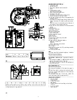
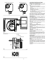
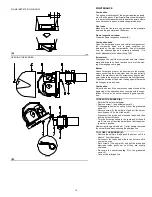
• The main gas train must be connected to the gas
attachment 1)(A), using flange 2), gasket 3) and
screws 4) supplied with the burner.
• The main gas train can enter the burner from the right
or left side, depending on which is the most conven-
ient, see fig.(A).
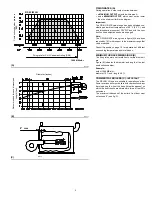
• Gas safety shut-off valves 5)-6)(B) must be as close
as possible to the burner to ensure gas reaches the
combustion head within the safety time range.
• The pilot gas train must be connected to the gas
attachment 5)(A) and can enter the burner from the
right or left side.
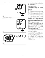
GAS TRAIN (B)
It must be type-approved according to required local-
standards and is supplied separately from the burner.
Note
See the accompanying instructions for the gas train lay-
out.
KEY (B)
1 - Gas input pipe
2 - Manual valve
3 - Pressure regulator
4 - Low gas pressure switch
5 - 1st safety shut off valve
6 - 2nd safety shut off valve
7 - Standard issue burner gasket with flange
8 - Gas adjustment butterfly valve
9 - Burner
(A)
(B)
TYPICAL SCHEMATIC GAS PIPING
GAS PILOT LINE
MAIN GAS LINE
D2293
D2294
1
3
2
4


