- 14 -
P
OWER
C
ONNECTION
ATTENTION: BEFORE PROCEDING WITH THE FOLLOWING OPERATIONS, MAKE SURE THAT THE CPS
IS COMPLETELY OFF AND DISCONNECTED FROM THE MAINS AND ANY LOAD.
ALL OPERATIONS DESCRIBED IN THIS SECTION MUST BE PERFORMED BY QUALIFIED PERSONNEL
ONLY. Our Company assumes no liability for damages caused by incorrect connections or operations
not contained in this manual.
The CPS and the Battery Cabinet contains HAZARDOUS electrical voltages inside them, even when the
input and/or battery switches are off. The internal parts are protected by safety panels which can be
removed by trained personnel only. All installation and maintenance or operations involving access
inside the CPS or Battery Cabinet require the use of tools and may ONLY be performed by trained
personnel.
To carry out the following operations, the CPS must be disconnected from the mains power supply,
switched off, and with all the equipment switches and fuse holders open. Check that there are no Battery
Cabinets connected to the CPS, if this is the case open all their fuse holders.
I
NSTRUCTIONS FOR CONNECTION
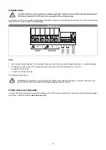
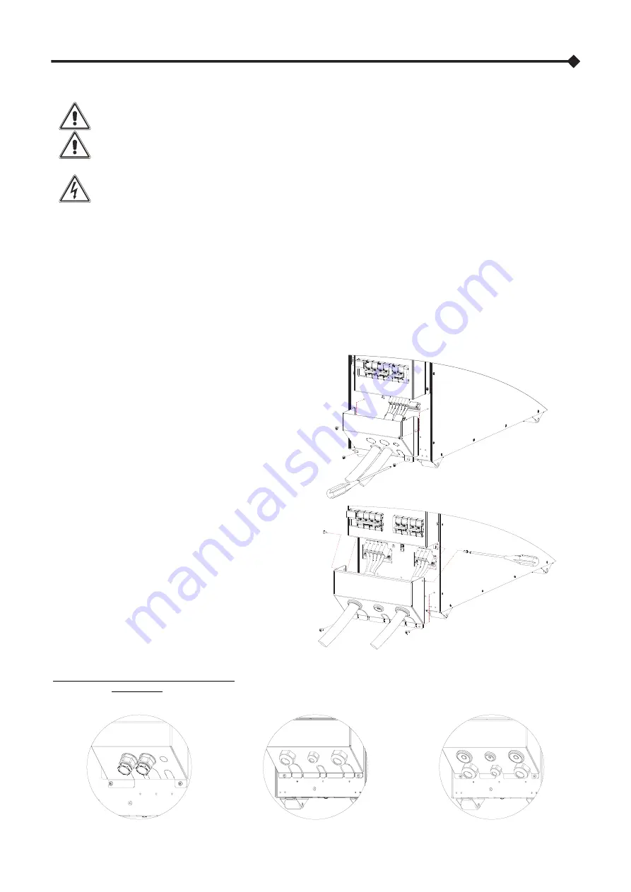
Follow the instruction below to access the terminals of the CPS and made the electrical connections:
1. Remove the terminals cover in the back of the CPS,
placed below the disconnector switches (see
"CPS
VIEWS
")
2. Pierce the rubber grommets to allow the wires to
pass through, otherwise remove the pre-cut slots
(located in the bottom part of the terminal cover)
using cutters.
3. We recommend using double-insulated multi-core
cables to be connected, respectively, to the “INPUT”
and “OUTPUT”.
4. For the cross section and the cable stripping, refer
to the paragraph "
C
ONNECTION CABLES CROSS
SECTION DETAILS
5. The wires should be stripped and inserted into the
terminals (for the length of the stripping, refer to the
paragraph “
C
ONNECTION CABLES CROSS SECTION
DETAILS
”).
NOTE:
To remove the wire, insert a flat blade
screwdriver into the clamp slot above the wire inlet.
6. Fix the cables to the ties block in the back of the
CPS.
7. When the installation is complete, close the
terminals cover and secure with the screws
Option with cable glands (not supplied):
Cable glands (not supplied) can be used to secure the cables, using the pre-cut holes in the terminal cover; refer to the example
images below. To remove the pre-cut disks use a suitable pair of cutters.
Summary of Contents for CSS SENTINEL TOWER CAM 3
Page 1: ......
Page 2: ......
Page 6: ... 4 ...
Page 8: ... 6 CPS VIEWS FRONT VIEW All models Display panel Removable front panel Ventilation grill ...
Page 39: ......
Page 40: ...0MNCAM3K0RUENUB ...


