- 17 -
C
ONNECTIONS
The first wire to be connected is the protective earth wire, which is to be inserted in the terminal marked
PE. During operation the CPS must be connected to the earthing system
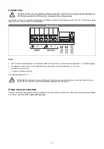
Connect the cables to the terminals following the information provided on the label placed upon the CPS. In the images below
there are some notes in relation to the installation:
Models 3-5 kVA
NOTE
1. If an "external manual bypass" is not provided, make sure that there is a jumper between terminals 1 - 2 (Switch bypass).
2. The maximum cross section of the cables that may be inserted in the terminal board 1, 2, 3 & 4 are:
- 2.5 sqmm for bare cables
- 1.5 sqmm for cables with lugs.
The stripping length is 8 mm
WARNING! Pay attention to connect the input neutral (N
IN
) and output neutral (N
OUT
); incorrect connection could
cause a failure of the load when the Maintenance Bypass switch is closed.
O
THER INSTALLATION MODES
For more information regarding the parallel installation of the CPS, isolation transformers, accessories for maintenance Bypass
and others, consult the website
www.riello-ups.com
.
Summary of Contents for CSS SENTINEL TOWER CAM 3
Page 1: ......
Page 2: ......
Page 6: ... 4 ...
Page 8: ... 6 CPS VIEWS FRONT VIEW All models Display panel Removable front panel Ventilation grill ...
Page 39: ......
Page 40: ...0MNCAM3K0RUENUB ...


