page 18 / 85 0MLMHTM16RUENUB
1.1.2
Connection of Power Cables for Single input Unit
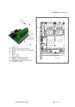
Connect the input, output and battery cables to the terminals as shown in the figure below:
MASTER HP – UL Power connection Terminals
Note: For the Input, Output and Battery connections, follow the order from the top to bottom, or right to left, as
described in the boxes. The label marked “N” present on the terminal identifies the neutral terminal.
The single input is a factory default configuration. Do not remove the bypass jumper. The input phase
connections are made using bolts to one of the three holes in the bus bar. Do not loosen the bolts that attach the
bus bar.
Bond: The UPS is provided with a separate bus bar that connects the Neutral Output to the frame Ground for
delta input connection. This is required to meet NEC grounding code for separately derived neutrals. When a
Neutral is provided in a Wye configured input connection the bus bar should be removed.
Refer to NEC article 250 (Grounding and Bonding) for identify system of grounding and size of equipment
grounding conductor
Once installation has been completed inside the equipment, put the switch cover panel back and close the door.


