page 44 / 85 0MLMHTM16RUENUB
1.1.21 Emergency power off device (EPO)
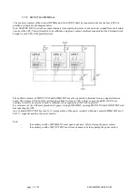
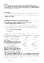
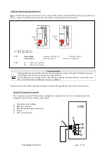
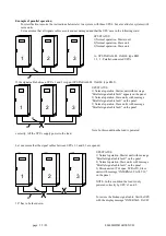
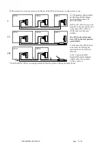
When several devices are connected in parallel, the EPO command must be sent to all UPS’s simultaneously, as shown
in the figure below:
a - EPO terminal board on the UPS
b- EPO switch with auxiliary contacts (not provided).
The button must have the same number of auxiliary contacts as the number of parallel UPS’s. Each UPS must have the
jumper on the EPO terminals removed and the wires from the auxiliary contact of the button must be connected instead
of the jumper.
The contact must be N.C. with the button in the rest position and be opened when the button is pressed.
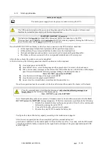
Installation of the EPO switch must be made with the UPS’s turned off.
1.1.22 External maintenance bypass.
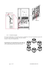
In some cases, in order to facilitate maintenance operations of the individual units making up the system, it may be
advisable to install an external maintenance bypass.
The External Maintenance Bypass should be installed in accordance with the manual for the External Maintenance
Bypass Cabinet
4.15
Mains, and load connections.
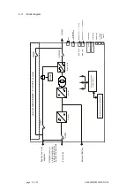
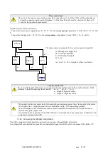
All the information contained in the section “Mains, load and battery connections” (page 27) in relation to the UPS
remains valid with the addition of the information set out below.
1.1.23 UPS AC input / output power connection
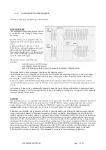
Refer to the Electrical Connections (Section 4) of this manual for information on how to size the cables for
each UPS
.
UPS 1
a
UPS 2
a
UPS 8
a
b


