0MLMHTM16RUENUB page 45 / 85
Phase connections
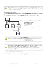
Phase L1 of the mains source must be connected to input phase L1 on all the UPS’s; all the output phases
L1 must be connected together and with phase L1 of the load. This rule must be observed for phases L2,
L3 and for the input and output neutral.
Parallel connect the UPS as follows:
- Connect the mains power supply phases L1, L2, L3, N to the
corresponding
input phases of each UPS L1, L2, L3, and
N.
- Connect the load phases L1, L2, L3, N to the
corresponding
output phases of each UPS L1, L2, L3, and N.
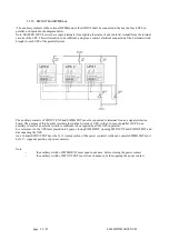
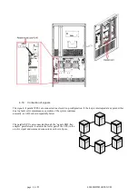
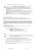
The figure shows an example of three units connected in parallel.
A)
Mains power supply line
B)
UPS input terminals
C)
UPS output terminals
D)
Load
(a1, a2, a3, c1, c2, c3) length of cables (see below)
Length of cables rule
The sum of the lengths of the mains power supply and output cables must be the same for all units. With
reference to the above drawing, these must be: a1+c1 = a2+c2 = a3+c3
a = length of input line cables
c = length of output line cables
The length of cables rule must also be followed with separate mains power lines: the lengths of the cables
of the bypass line + output line must be the same between all the UPS connected in parallel.
Lack of compliance with this rule may cause a current imbalance between the UPS’s when the load is
powered through the bypass line.
An overload on the bypass line of one UPS will lead to a deterioration of the components on that line, both
internal and external to the UPS.
1.1.24 Connecting the Parallel Card (Option)
The UPS is supplied with the parallel control cards on request or the parallel kit is provided.
For all details about installations of parallel card and parallel signal card RJ45 refer to the manual “Parallel kit UL”
OUT (C)
MAINS (A)
a2
c3
IN (B)
IN (B)
OUT (C)
a1
a3
2
c1
3
IN (B)
1
D
OUT (C)
c2
UPS 1
UPS 2
UPS 3


