page 70 / 85 0MLMHTM16RUENUB
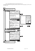
The "end of discharge pre-alarm" contact for remote alarms is also switched.
In this case the system remains active for the next 4 minutes, after that the system switches onto the bypass line and
then deactivates.
There is no output voltage after deactivation.
The interval between the start of the alarm and deactivation is equal to the interval selected as PRE-ALARM.
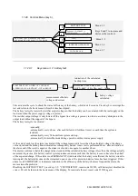
When the internal clock reaches the time Ton (7:00'), if the mains voltage is present, the system automatically
reactivates and returns to normal operation.
1.1.29.9
BYPASS VOLTAGE RANGE ADJUSTMENT
Press the following sequence of keys to access the menu: 3,5,436215, 7, 2:
Press key 1 to exit the menu. Keys 7 and 8 can be used to decrease or increase the value, as a percentage, of the
acceptable range for the voltage at the bypass line input, with respect to the rated output value.
With the UPS in standby-ON mode, the menu is as follows:
(StbyON=15%) BY. VOLTAGE RANGE = +/- 15%
ADJUSTMENT: (5-, 6+) 7=-, 8=+
Keys 5 and 6 can be used to reduce or increase the percentage of the acceptable range of the bypass voltage in STBY
ON mode.
1.1.29.10
BYPASS FREQUENCY RANGE ADJUSTMENT
Press the following sequence of keys to access the menu: 3,5,436215,7, 3:
Press any key other than 7 or 8 to exit the menu. Keys 7 and 8 can be used to decrease or increase the value, as a
percentage, of the acceptable range for the frequency at the bypass line input. The choice has the range from +/- 1%, to
+/- 5% of the nominal value 60 Hz.
1.1.29.11
MODEM
Press the following sequence of keys to access the menu: 3, 5, 436215,7, 4:
MODEM enable = 0,
ADJUSTMENT: (5=dial, 6=send) 7=-, 8=+
Press key 1 to exit the menu.
Keys 7 and 8 can be used to decrease or increase the control value for management of the modem. The choice is
between the values of 0 to 5. The initial value is 0.
0 =
the modem connected to the RS232 port is deactivated. Terminal 20 of the RS232 connector assumes a low level (-
12V) (DTR signal deactivated).
NOTE
the configuration MODEM=0 is essential when the modem is not used and the RS232 connector is used for
connection to the remote panel.
1=
signal DTR is activated (terminal 20 at +12V), the modem is enabled to reply (it should be remembered that a
remote panel connected to the RS232 connector in place of the modem remains off).
2=
signal DTR is activated, the modem is ready to reply and for automatic calls.
After an "internal fault" alarm has been on for 30 seconds, the system automatically dials the stored "DIAL" number.
When it receives the modem’s receiving reply it sends a message made up of the UPS acronym, the stored "SEND"
number, a copy of the text shown on the display, the alarm code and the date and time of transmission.

