Pag. 27 a 83
0MLMHTK65RUENUB
Connection of signals and remote commands
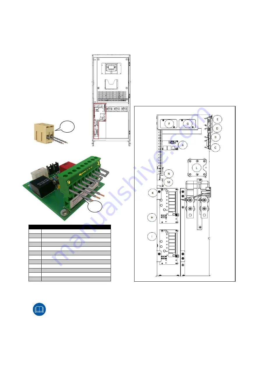
In order to access the interface cards, open the door and remove the protection panel secured with screws (K) as
shown in the drawing:
REF.
DESCRIPTION
A PARALLEL
B
EPO (Emergency Power Off control)
C
REMOTE COMMANDS AND ALARMS
D
RS232-2
E RS232-1
F
SLOT 2 (aux)
G
SLOT 1 (main)
H
REMOTE ALARMS #1(optional)
I
REMOTE ALARMS #2(optional)
L
MODEM (optional) or MULTI I/O (optional)
M
AUX SIGNALS ISOLATION BOARD
N
TERMINAL BLOCK
AUX SIGNALS ISOLATION BOARD allows receiving external auxiliary contacts and keeping them
isolated from the UPS internal circuits making easy connections in case of paralleling of the units.
Jumpers AUX (SWBATT, SWMB, SWOUT) must be connected to the terminal of the board if no
external auxiliary contacts are presents.
N
M


