page 33 / 84
0MLMHTM30RUENUA
1
2
3
4
5
6
7
8
9
1
2
3
4
5
6
7
8
9
1
2
3
4
5
6
7
8
9
1
2
3
4
5
6
7
8
9
female
femmina
db9
female
femmina
db9
male
maschio
db9
male
maschio
db9
UPS
RS232-2
Computer
1
2
3
4
5
6
7
8
9
1
2
3
4
5
6
7
8
9
1
2
3
4
5
6
7
8
9
1
2
3
4
5
6
7
8
9
female
femmina
DB9
female
femmina
DB9
male
maschio
DB9
male
maschio
db9
UPS
RS232-2
Modem
DB9 male RS232-1
- E -
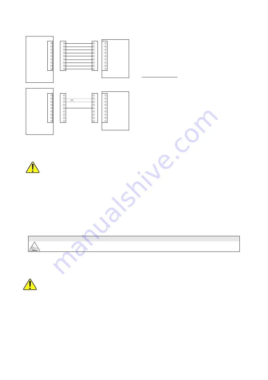
For connection with a modem use a cable
standard.
See the diagram for connection with a computer.
5.5.3 SLOTS 2-1, the following cards may be inserted (optional):
-F, G-
NetMan 204
(on SLOT 1 main or SLOT 2 aux)
SELV CIRCUIT PROVIDED.
CONNECT TO SELV CIRCUIT ONLY.
Device for management of the UPS’s on the Ethernet. It can send information on the status of the device with different
protocols:
TCP/IP UDP (compatible with Watch&Save);
SNMP (for communications with NMS or with PowerNETGuard);
HTTP (to display the status with a browser);
TFTP (to configure or update the device when connected to the network).
The main function of this device is to integrate the UPS into the LAN network ensuring a high level of reliability of
communication with the server to enable full management and control of the UPS.
For the full and updated list of communication accessories, please see the website www.riello-ups.com.
5.5.4 REMOTE ALARMS (2 optional cards for the MASTER HP–UL)
SELV CIRCUIT PROVIDED.
CONNECT TO SELV CIRCUIT ONLY.
- H, I -
6 outputs: dry contacts for alarms (programmable from the display panel) (they are capable of switching up to
30 V AC/DC and up to 1A), 2 inputs (programmable from the panel) and 1 12V DC maximum 100mA auxiliary
input.
5.5.5 Battery temperature sensor (optional)
-M-
The UPS has an input available on the auxiliary signals isolation board, for the kit which consists of a sensor to be
placed inside the battery cabinet. The use of the temperature sensor allows the UPS control logic to adjust the values of
the charge and maintenance voltage according to the actual temperature of the battery.


