background image


0ML190480RUENUC 


page   22 / 24 


AUXILIARY CABLES CONNECTIONS (OPTION) 


The signals described in this paragraph are not part of safety circuit, since they are 
not insulated from dangerous voltage.  

Do not connect to SELV circuit  

Connect to UPS only using the cables provided (600V minimum rating)

.                         


Circuit breaker interface 

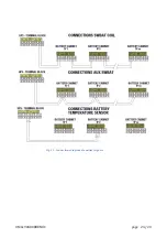
1)  If opening of Battery Circuit Breaker is required for EPO (Emergency Power Off) operation, Terminals 

SWBAT COIL must be connected to terminals SWBAT COIL of UPS cabinet. 
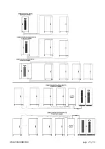
In case of 2 or more Battery Cabinets Installed, connect terminals SWBAT COIL of second Battery   

Cabinet to SWBAT COIL II of first battery cabinet and so on (see Fig.  15) 

2)  Battery Circuit Breaker Open, aux contact signal requires: 

Connect terminals AUX SWBAT to terminals AUX SWBAT of UPS cabinet.  
In case of 2 or more Battery Cabinet installed, connect the terminals in parallel (see Fig.  15).  


For connection of these signals, 2 cables 22AWG style 2516 (600V) are supplied, as listed in       
section 3  


Temperature sensor (option) for adjusting charging voltage 

 
The battery cabinet is provided with a temperature sensor kit, when this option is present. 
If the compensation of charging voltage, as function of Battery Cabinet temperature, is required,  
connect terminals “Battery Temp.Sensor” to terminal “Battery Temp.Sensor” of UPS cabinet, using shielded 
cable 2x 22awg style 4516, supplied as in the component list, section 3 see. 


In case of two or more Battery Cabinets installed, only one temperature sensor must be connected .    


Summary of Contents for MASTER HP

Page 1: ...UNINTERRUPTIBLE POWER SUPPLY MASTER HP UL 55 100Ah BATTERY CABINET User Manual ...

Page 2: ...0ML190480RUENUC page 2 24 RPS SpA Viale Europa 7 37045 Legnago VR Italy www riello ups com ...

Page 3: ...ODE 11 REMOVE TRAYS 12 POSITIONING AND INSTALLING BATTERIES 12 TRAY ASSEMBLY PROCEDURE 13 CONNECTION BETWEEN THE TRAYS 15 SECTION 5 19 CONNECTION TO UPS SYSTEM 19 POWER CABLE CONNECTION 19 AUXILIARY CABLES CONNECTIONS OPTION 22 SECTION 1 INTRODUCTION The BBX battery cabinet is used along with the Uninterruptible Power Supply UPS series MHT to prevent loss of valuable electronic information and min...

Page 4: ... manual cover the versions BBX 1900 480V UL L6 3U 55 Ah Rated Voltage 480Vdc 240 cells 40x 12Vdc blocks OCP 200 A Circuit breacker provided Suitable for up to 80kVA MHT UPS BBX 1900 480V UL L8 3U 100 Ah Rated Voltage 480Vdc 240 cells 40x 12Vdc blocks OCP 300 A circuit breaker provided Suitable up to 160kVA MHT UPS up to 500kVA with 2 or more strings Fig 1 BBX battery cabinet external dimensions ...

Page 5: ...LLOW ALL SAFETY INSTRUCTIONS a Do not use outdoors b Do not route wiring across or near hot surfaces c Do not install near gas or electric heaters d Use caution when servicing batteries Battery acid can cause burns to skin and eyes If acid is spilled on skin or in eyes flush with abundant fresh water and contact a physician immediately e Equipment should be installed where it will not readily be s...

Page 6: ...posed to flame This product contains Valve Regulated Sealed Acid Batteries Do not open or mutilate batteries Released material is harmful to the skin and eyes It may be toxic These batteries contain lead a neurotoxin and sulfuric acid a corrosive Additionally the energy stored in the batteries can present a shock hazard and a burn hazard Batteries should only be serviced by trained personnel A bat...

Page 7: ...ted to no more than 30 days per year Under no circumstances should the battery be exposed to temperatures over 104 F 40 C which can lead to thermal runaway a condition that damages the battery Thermal runaway can cause batteries to swell and if the battery body burst the hazardous contents may be exposed MAINTAINING PROPER AMBIENT TEMPERATURE USUALLY REQUIRES INSTALLING THE PRODUCT IN A TEMPERATUR...

Page 8: ... Battery Cabinet without batteries Maximum Weight 300kg 662 lbs CLEARANCES The following clearances are recommended for the Battery Cabinet Front of Cabinet 150 cm 59 working space Back of Cabinet 15 2 cm 6 HANDLING THE CABINET unloading and transporting The cabinet can be shipped including the batteries installed inside or without batteries On table 2 are reported the weights of cabinets with and...

Page 9: ...maximum separation 5 Keep the people out of the area of possible fall of the cabinet during unloading and through path of destination 6 Lift the cabinet with forklift 1or 2 inches 1 2 2 5 5cm from the floor level 7 Carefully move the cabinet to location where will be installed and slowly drop off it to the floor or other appropriate flat surface Fig 2 lag bolts Fig 3 position the forks in the indi...

Page 10: ... Cable 1 0 or 2x1 0 AWG length 360mm 14 17 in crimped to blue connector at one side 2pcs 4 Red and black cable 2x 22 AWG style 1015 800mm 31 5 in 5 Shielded cable 2x 22 AWG style 4516 25m 82 ft Option 6 2 x Cable 2x22 AWG style 2516 7 Cu busbar marked 1 N 10 8 Cu busbar marked 2 N 20 9 Cu busbar marked 3 N 5 10 Cu busbar marked 4 N 10 11 Screws washers and spring washer to connect busbars to batte...

Page 11: ... Remove all metal wearable objects rings watches bracelets necklaces Appropriate eye protections must be worn Tools with insulated handles only must be used If electrolyte leaking from batteries comes into contact with the skin wash immediately the part with abundant clean water Type of batteries to be used Cabinet size model Manufacturer P N n of units Cells per unit unit rated voltage 100 Ah BBX...

Page 12: ...d POSITIONING AND INSTALLING BATTERIES Use the components supplied inside the cabinet and listed in the previous section position 1 15 to assembly the trays following the procedure below See the Table 3 torque values to connect busbars to batteries blocks terminal and lugs to busbar terminal Tray n 1 must be assembled inside the cabinet Trays n 2 3 4 5 to facilitate the assembly the operations can...

Page 13: ...ten tubing over the terminal using a cable tie Connect Positive and negative terminal of the assembled tray with a cable pos 1 3 having colored connector at one side fig 5 Choose the color of the connector according with number of the tray and polarity as described below Tray n 1 terminal grey or green terminal blue Tray n 2 terminal grey or green terminal grey or green Tray n 3 terminal red termi...

Page 14: ...0ML190480RUENUC page 14 24 Part Fig 7 100Ah tray Fig 7bis 55Ah Fig 8 bus bars references Fig 9 battery tray assembled Fig 10 Insulating sheet fixed with cable ties for covering bare bars of batteries ...

Page 15: ...1 TRAY 2 Connect each other the grey or green connectors TRAY 1 CIRCUIT BREAKER Connect the blue connectors TRAY 2 TRAY 3 Connect grey or green connectors TRAY 3 CIRCUIT BREAKER Connect the red connectors TRAY 4 CIRCUIT BREAKER Connect the blue connectors TRAY 4 TRAY 5 Connect the grey or green connectors TRAY 5 CIRCUIT BREAKER Connect the red connectors Fig 11 detail of fastening ...

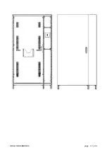
Page 16: ...0ML190480RUENUC page 16 24 Fig 13 Battery cabinet assembled Color table connectors Colors Abbreviation Blue BL Red RD Gray GY Green GN When the Battery Cabinet is full assembled reinstall all panels ...

Page 17: ...0ML190480RUENUC page 17 24 ...

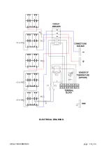
Page 18: ...0ML190480RUENUC page 18 24 ELECTRICAL DRAWING ...

Page 19: ...ted copper wire Minimum wire size is based on full load ratings applied to NEC Code Table 310 16 Code may require a larger AWG size than shown in this table because of temperature number of conductors in the conduit or long service runs Follow local requirements CABLE ENTRY OF BATTERY CABINET IS PROVIDED EITHER FROM BOTTOM OR TOP Only properly trained and qualified personnel should perform the UPS...

Page 20: ...0ML190480RUENUC page 20 24 ...

Page 21: ...0ML190480RUENUC page 21 24 ...

Page 22: ...e Fig 15 2 Battery Circuit Breaker Open aux contact signal requires Connect terminals AUX SWBAT to terminals AUX SWBAT of UPS cabinet In case of 2 or more Battery Cabinet installed connect the terminals in parallel see Fig 15 For connection of these signals 2 cables 22AWG style 2516 600V are supplied as listed in section 3 Temperature sensor option for adjusting charging voltage The battery cabine...

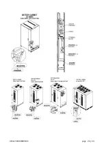
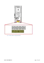
Page 23: ...0ML190480RUENUC page 23 24 Fig 14 battery cabinet terminal block detail ...

Page 24: ...0ML190480RUENUC page 24 24 Fig 15 Connections diagram of auxiliary signals ...

Reviews: