‐ 50 ‐
“B
YPASS
M
ODULE
”
P
AGE
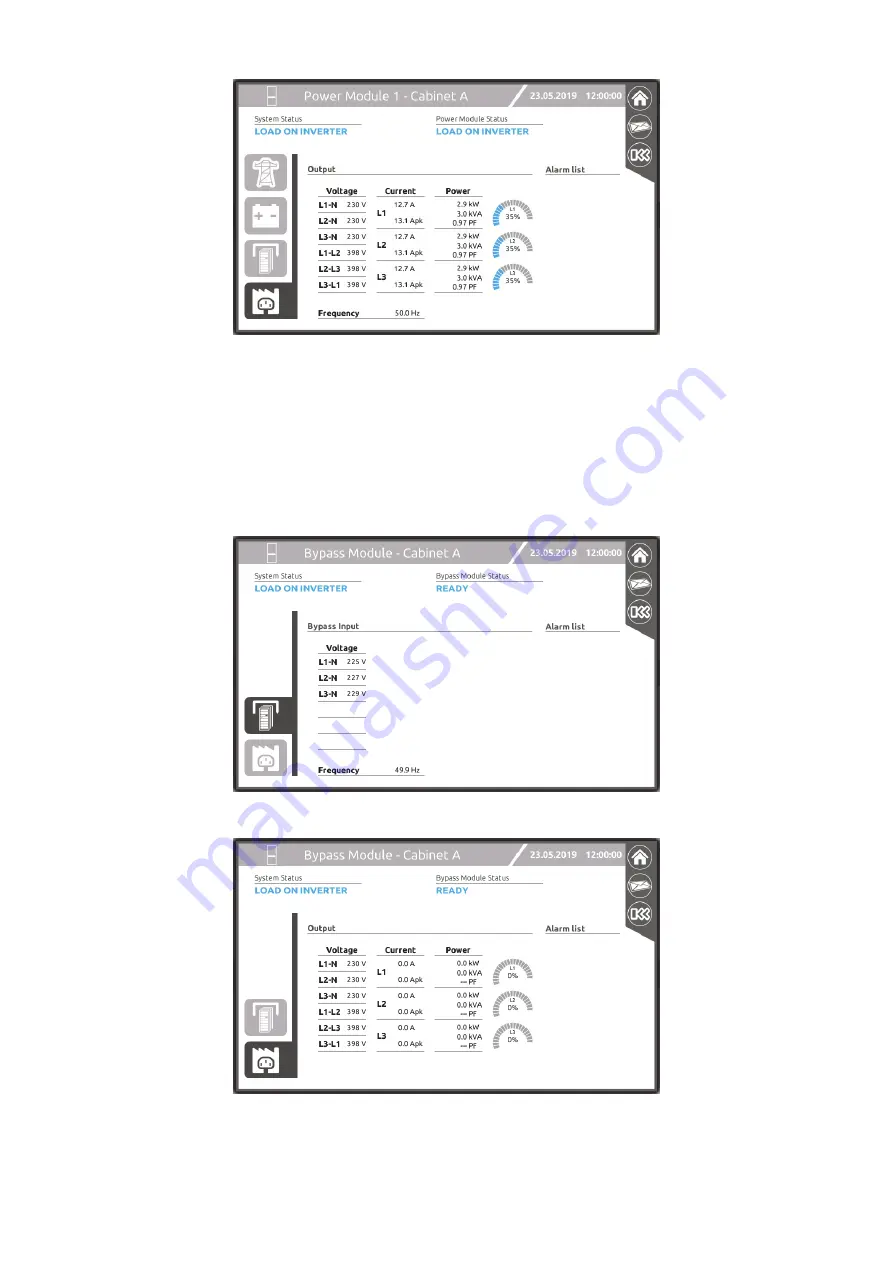
The frequency and voltage of each phase are displayed on the bypass input values page.
The bypass voltages and currents are displayed in the output values page. During inverter mode operation, bypass currents are
always zero, while the voltages on the bypass output will be visible. Alternatively, during normal bypass operation and in presence
of a load, the bypass current values will reflect the load levels applied.
The alarm list on the right of the page shows details of any anomalous conditions/alarms currently present on the selected BM.
Summary of Contents for MPX 100 CBC
Page 1: ......
Page 2: ......
Page 8: ... 6 Top view Bottom view Display Wheels Bottom cable entry Fastening stands ...
Page 19: ... 17 A wring diagram of the Modular UPS Power Cabinet is provided below ...
Page 22: ... 20 The wiring diagram of the Modular UPS Combo Cabinet is provided below ...
Page 54: ... 52 Combo Cabinet MPX 100 CBC ...
Page 55: ... 53 Battery Cabinet MPW 170 BTC ...
Page 73: ... 71 MONITORING VIA WEB BROWSER ...
Page 91: ......
Page 92: ...0MNMPXK15RUENUB ...


