64
U
SE
C
ONNECTIONS
INSTALLATION MUST BE CARRIED OUT EXCLUSIVELY BY QUALIFIED PERSONNEL.
THE FIRST CONNECTION TO BE CARRIED OUT IS THE PROTECTION CONDUCTOR (EARTH CABLE), TO BE
INSERTED IN THE TERMINAL MARKED
.
THE UPS MUST NOT BE OPERATED WITHOUT BEING CONNECTED TO THE EARTHING SYSTEM.
Warning:
if the neutral (N) and phase (F) instructions are observed for the plugs and sockets, the UPS will
not change the existing neutral arrangements when inserted in a system. The resistance on the neutral
connection is less than 0.1 ohm.
A differential switch placed upstream will also be triggered for a fault occurring downstream of the UPS.
The sensitivity of this switch has to take into account the leakage current of the unit (approx. 2 mA) and of
the load which are added together on the UPS earth conductor.
UPS input
Differential switch
Single-phase
Type B or Type A
Three-phase
Type B
The neutral arrangements will only be changed if an isolation transformer is connected or when the UPS is
operating with the neutral isolated upstream.
Avoid connecting the output neutral to the input neutral or to earth as this could damage the UPS .
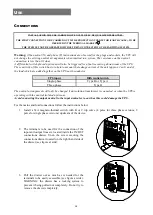
For the mains and load connections follow the instructions below:
1.
Install a 63A magneto-thermal switch with B or C trip curve (4 poles for three phase versions, 2
poles for single phase versions) upstream of the device.
2.
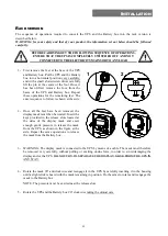
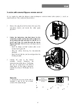
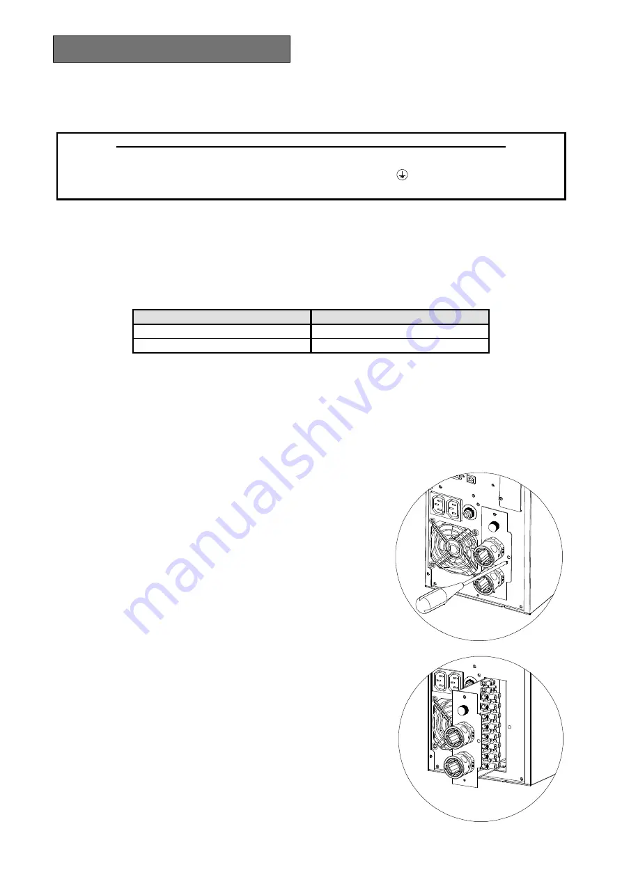
The terminals to be used for the connection of the
input and output lines are located inside the IN/OUT
connections drawer. Undo the screw securing the
connections drawer located on the right-hand side of
the drawer (see figure at side).
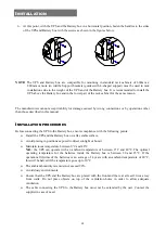
3.
Pull the drawer out as much as is needed for the
terminals to be easily accessible (see figure at side).
WARNING: the drawer has a locking system to
prevent it being pulled out completely. Do not try to
remove the drawer completely.
Summary of Contents for SENTINEL DUAL SDL 10000
Page 1: ......
Page 2: ......
Page 4: ...4 ...
Page 14: ...14 ...
Page 15: ...15 I MANUALE D USO I ...
Page 50: ...50 ...
Page 51: ...51 GB USER MANUAL GB ...
Page 86: ...86 ...
Page 87: ...87 D BEDIENUNGSANLEITUNG D ...
Page 122: ...122 ...
Page 123: ...123 F MANUEL DE L UTILISATEUR F ...
Page 158: ...158 ...
Page 159: ...159 E MANUAL DE USO E ...
Page 194: ......
Page 195: ......
Page 196: ...0MNSDL6K5RU5LUC ...


